Product Description
Product Description
Shaft mounted speed reducer helical gear box reduction gearbox
1. Product Characteristics
(1) Strong alloy steel, hardened, ground on journals, gear seatings and extensions, for maximum load and maximum torsional loads. Generous size shaft keys for shock loading and conform to iso standards.
(2) Standard or alternative hubs with metric bores are available to suit international standard shaft diameters.
(3) Strong alloy materials for high load capacity, carburizing and quenching, ground profile(some intermediate pinions are shaved) CZPT tooth profile, 98% efficiency for per stage, smooth quiet operation with several teeth in mesh.
(4) Close grain cast iron construction, excellent vibration dampening & shock resistance features, precision bored and dowelled to ensure accurate in-line assembly.
(5) Eliminates the need for critical tightening of torque arm bolts, controls position of standard torque arm mounting within recommended.
(6) Bearings are adequately proportioned and conform to iso dimension plan, readily available world-wide. Oil seals are double garter spring type, ensuring effective oil sealing.
(7) Self sealing intermediate cover plates, to standard iso housing dimensions.
(8) Alternative parts, anti-run back device, are available on bothl 13:1 and 20:1 ratio units and do not recommend for 5:1 units.
(9) To adjust the install space location of reducer and the elasticity of belt.
The models of SMR shafted mounted gearbox: B,C,D,E,F,G,H,J series shaft mounted gearbox
Detailed Photos
Product Parameters
| Rated Power |
Gear Arrangement | Output Speed | Ratio | Back-stop |
| 0.29KW~134KW | Helical Hardened Gearbox | 10~400r/min | I=1/5,1/13,1/20 | Alternative parts, Anti-runback device |
Packaging & Shipping
Company Profile
Our Advantages
Our Services:
| Pre-sale services | 1. Select equipment model. |
| 2.Design and manufacture products according to clients’ special requirement. | |
| 3.Train technical personal for clients | |
| Services during selling | 1.Pre-check and accept products ahead of delivery. |
| 2. Help clients to draft solving plans. | |
| After-sale services | 1.Assist clients to prepare for the first construction scheme. |
| 2. Train the first-line operators. | |
| 3.Take initiative to eliminate the trouble rapidly. | |
| 4. Provide technical exchanging. |
FAQ
1.Q:What kinds of gearbox can you produce for us?
A:Main products of our company: UDL series speed variator,RV series worm gear reducer, ATA series shaft mounted gearbox, X,B series gear reducer,
P series planetary gearbox and R, S, K, and F series helical-tooth reducer, more
than 1 hundred models and thousands of specifications
2.Q:Can you make as per custom drawing?
A: Yes, we offer customized service for customers.
3.Q:What is your terms of payment ?
A: 30% Advance payment by T/T after signing the contract.70% before delivery
4.Q:What is your MOQ?
A: 1 Set
If you have any demand for our products please feel free to contact me.
/* January 22, 2571 19:08:37 */!function(){function s(e,r){var a,o={};try{e&&e.split(“,”).forEach(function(e,t){e&&(a=e.match(/(.*?):(.*)$/))&&1
| Application: | Machinery, Industry |
|---|---|
| Hardness: | Hardened |
| Installation: | Horizontal Type |
| Layout: | Parallel |
| Gear Shape: | Helical |
| Step: | Double-Step |
| Customization: |
Available
| Customized Request |
|---|
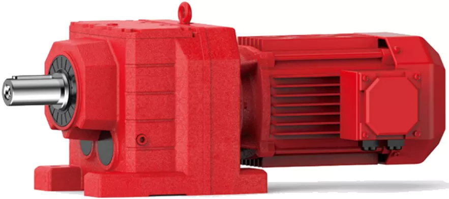
Types of Helical Gear Arrangements
Yes, there are different types of helical gear arrangements available to suit various applications and requirements. Some of the common helical gear arrangements include:
Parallel Shaft Arrangement: In this arrangement, the axes of the driving and driven shafts are parallel to each other. It is the most straightforward configuration and is often used in applications where space is not a constraint, and the gearboxes can be placed side by side.
Right-Angle Shaft Arrangement: In a right-angle arrangement, the driving and driven shafts are positioned at a 90-degree angle to each other. This arrangement is space-saving and is commonly used in applications where the layout requires a change in direction of the power transmission.
Double Helical Gear Arrangement (Herringbone Gears): Double helical gears consist of two sets of helical teeth facing each other. This arrangement helps to cancel out axial forces and reduces the net thrust load on bearings. It is often used in heavy-duty applications to minimize wear and vibration.
Crossed Helical Gear Arrangement (Screw Gears): In this configuration, the axes of the driving and driven shafts are neither parallel nor intersecting. It is suitable for applications requiring non-parallel and non-intersecting shafts.
The choice of helical gear arrangement depends on factors such as available space, power transmission requirements, and the desired layout of the machinery or equipment. Each arrangement has its advantages and disadvantages, and selecting the appropriate one is crucial for achieving optimal performance and efficiency.
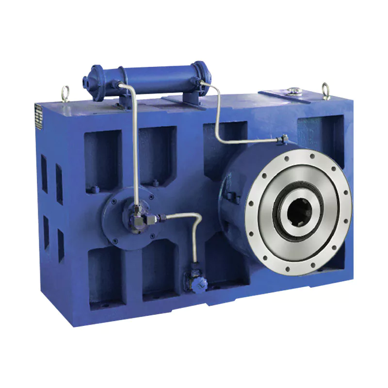
Troubleshooting Common Issues in Helical Gear Systems
Troubleshooting helical gear systems involves identifying and addressing common issues that can affect their performance. Here’s a step-by-step process:
- Visual Inspection: Begin by visually inspecting the gearbox for any signs of wear, damage, or misalignment. Look for worn or chipped gear teeth, oil leakage, and unusual noise.
- Noise Analysis: If noise is present, analyze its type and frequency. Whining or grinding noises could indicate misalignment or damaged gears, while clicking or knocking sounds might point to loose components.
- Lubrication Check: Ensure that the gearbox is properly lubricated with the recommended type and quantity of lubricant. Insufficient lubrication can lead to increased friction and wear.
- Alignment Check: Check the alignment of the gears and shafts. Misalignment can result in uneven wear, noise, and reduced efficiency. Realign components if necessary.
- Gear Inspection: Inspect gear teeth for signs of pitting, scoring, or wear. Replace any damaged gears to prevent further issues.
- Bearing Examination: Check the condition of bearings that support shafts and gears. Worn or damaged bearings can lead to increased vibration and noise.
- Tightening and Fastening: Ensure that all bolts, fasteners, and connections are properly tightened. Loose components can cause vibrations and noise.
- Load Analysis: Evaluate the load conditions and operating parameters of the gearbox. Ensure that the gearbox is not subjected to loads beyond its design capacity.
- Temperature Monitoring: Monitor the operating temperature of the gearbox. Excessive heat can indicate problems such as inadequate lubrication or overloading.
- Consulting Experts: If issues persist or if you’re unsure about the diagnosis and solution, consult gearbox experts or manufacturers for guidance.
By following this troubleshooting process, you can identify and resolve common issues in helical gear systems, ensuring optimal performance and longevity.
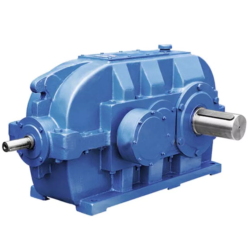
Limitations and Disadvantages of Helical Gear Systems
While helical gear systems offer numerous advantages, they also come with certain limitations and disadvantages:
- Axial Thrust: Helical gears generate axial thrust due to the helix angle of the teeth. This thrust can cause additional load on bearings and may require additional measures to counteract.
- Complex Manufacturing: The manufacturing process for helical gears is more complex than that of straight-toothed gears, which can lead to higher production costs.
- Axial Length: Helical gears require more axial space compared to spur gears with the same gear ratio. This can be a limitation in applications with space constraints.
- Sliding Contact: Helical gears have sliding contact between their teeth, which can result in higher friction and more heat generation compared to rolling contact gears.
- Efficiency: Although helical gears are generally efficient, their efficiency can be slightly lower than that of some other gear types, especially at high speeds.
- Complexity in Gearbox Design: The inclination of helical gear teeth introduces additional complexity in gearbox design and alignment.
- Reverse Thrust: In some cases, reverse thrust can occur when helical gears are subjected to high axial loads, leading to undesirable effects.
It’s important to consider these limitations and disadvantages when selecting gear systems for specific applications. Despite these challenges, helical gears remain a popular choice in various industries due to their benefits and overall performance characteristics.


editor by CX 2024-05-17
China manufacturer Foot Mounted CZPT Shaft Helical-Worm Gear Reducer /Gear Motor/Motor Reducer/Gear Units/Gearbox car gearbox
Product Description
Foot Mounted CZPT Shaft Helical-Worm Gear Reducer /Gear Motor/Motor Reducer/gear units/gearbox
< ABOUT TILI
Technical data
| Product Name | Foot Mounted CZPT Shaft Helical-Worm Gear Reducer /Gear Motor/Motor Reducer/gear units/gearbox |
| Power | 0.12KW~30KW |
| Nominal output torque | 9~ 8425N · m |
| Output speed | 0.1 ~ 374r/min |
| Gear material | 20CrMnTi alloy steel |
| Gear Processing | Grinding finish by HOFLER Grinding Machines |
| Noise Test | Below 65dB |
| Brand of bearings | C&U bearing, ZWZ, LYC, HRB, CZPT , etc |
| Brand of oil seal | NAK or other brand |
| Temp. rise (MAX) | 40ºC |
| Temp. rise (Oil)(MAX | 50ºC |
| Vibration | ≤20µm |
| Housing hardness | HBS190-240 |
| Surface hardness of gears | HRC58°~62 ° |
| Gear core hardness | HRC33~40 |
| Machining precision of gears | 5 Grade |
| Lubricating oil | GB L-CKC220-460, Shell Omala220-460 |
| Heat treatment | Carburizing, Quenching etc |
| Efficiency | 95%~96% (depends on the transmission stage) |
| Bearing output mode | Parallel output |
| Installation type and output mode | Bottom seated type flange type installation, solid,hollow shaft output. |
| Input mode | Direct motor, shaft input and connecting flange input |
| Input Method | Flange input(AM), shaft input(AD), inline AC motor input, or AQA servo motor |
Installation Instructions
Company Profile
< WORKSHOP
< QUALITY CONTROL
Certifications
Packaging & Shipping
FAQ
Q 1: Are you a trading company or a manufacturer?
A: We are a professional manufacturer specializing in manufacturing various series of reducer.
Q 2:Can you do OEM?
A:Yes, we can. We can do OEM for all the customers .if you want to order NON-STANDERD speed reducers,pls provide Drafts, Dimensions, Pictures and Samples if possible.
Q 3: How long is your warranty?
A: Our Warranty is 12 months under normal circumstances.
Q 4: Do you have inspection procedures for reducer?
A:100% self-inspection before packing.
Q 5: Can I have a visit to your factory before the order?
A: Sure, welcome to visit our factory.
Q 6:How to choose a gearbox? What if I don’t know which gear reducer I need?
A:You can refer to our catalogue to choose the gearbox or we can help to choose when you provide,the technical information of required output torque, output speed and motor parameter etc. Don’t worry, Send as much information as you can, our team will help you find the right 1 you are looking for.
Q 7: What information shall we give before placing a purchase order?
A:a) Type of the gearbox, Size , Transmission Ratio, input and output type, input flange, mounting position, motor information and shaft deflection etc. b)Housing color.c) Purchase quantity. d) Other special requirements
Q 8:What is the payment term?
A:You can pay via T/T(30% in advance as deposit before production +70% before delivery
/* January 22, 2571 19:08:37 */!function(){function s(e,r){var a,o={};try{e&&e.split(“,”).forEach(function(e,t){e&&(a=e.match(/(.*?):(.*)$/))&&1
| Application: | Motor, Machinery, Agricultural Machinery |
|---|---|
| Function: | Distribution Power, Change Drive Torque, Speed Changing, Speed Reduction |
| Layout: | Vertical Output |
| Customization: |
Available
| Customized Request |
|---|
.shipping-cost-tm .tm-status-off{background: none;padding:0;color: #1470cc}
|
Shipping Cost:
Estimated freight per unit. |
about shipping cost and estimated delivery time. |
|---|
| Payment Method: |
|
|---|---|
|
Initial Payment Full Payment |
| Currency: | US$ |
|---|
| Return&refunds: | You can apply for a refund up to 30 days after receipt of the products. |
|---|
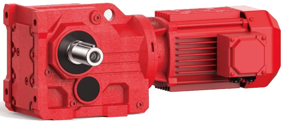
Using Helical Gearboxes for Speed Reduction and Speed Increase
Yes, helical gearboxes can be used for both speed reduction and speed increase in various applications. The design of helical gears allows them to transmit motion and power between non-parallel shafts while changing the rotational speed.
Speed Reduction: When the driving gear (pinion) has fewer teeth than the driven gear, the gear ratio leads to speed reduction. This is commonly used in applications where the input speed needs to be decreased while increasing the output torque. For example, helical gearboxes are often employed in conveyor systems to reduce the speed of the motor while maintaining sufficient torque to move heavy loads.
Speed Increase: Helical gearboxes can also achieve speed increase by having the driving gear (pinion) with more teeth than the driven gear. This configuration is less common but can be used to increase the output speed while sacrificing some torque. Speed increase applications are typically seen in scenarios where higher speeds are required, such as in certain types of machinery or industrial processes.
It’s important to note that while helical gearboxes can perform both speed reduction and speed increase, the specific gear ratios and configurations need to be carefully chosen to ensure efficient and reliable operation for the intended application.
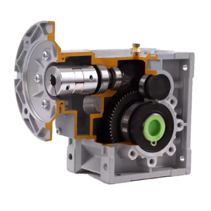
Safety Precautions for Operating Machinery with Helical Gear Systems
When operating machinery equipped with helical gear systems, it’s crucial to prioritize safety to prevent accidents and ensure the well-being of operators and equipment. Here are the key safety precautions to consider:
- Training and Familiarity: Operators should receive proper training on the equipment’s operation, including the helical gear system. They should be familiar with the controls, emergency procedures, and potential hazards.
- Protective Gear: Operators should wear appropriate personal protective equipment (PPE), such as gloves, safety glasses, helmets, and ear protection, depending on the application’s requirements.
- Lockout/Tagout: Before performing maintenance or repairs, follow lockout/tagout procedures to isolate the machinery from its power source and prevent accidental startup.
- Regular Inspections: Conduct routine inspections of the helical gear system and other machinery components to identify signs of wear, damage, or malfunction. Address any issues promptly to avoid unsafe conditions.
- Proper Lubrication: Ensure the helical gear system is adequately lubricated according to manufacturer recommendations. Proper lubrication reduces friction, wear, and heat buildup, enhancing both performance and safety.
- Emergency Stop: Machinery should be equipped with clearly marked emergency stop buttons or switches that operators can use to halt operations immediately in case of an emergency.
- Cleaning and Housekeeping: Maintain a clean work environment by removing debris, oil spills, and other potential hazards. Good housekeeping minimizes slip and trip hazards and promotes safe operation.
- Load Capacity: Adhere to the recommended load capacities specified by the manufacturer for both the helical gear system and the machinery as a whole. Overloading can lead to accelerated wear and potential failures.
- Avoid Loose Clothing: Operators should avoid wearing loose clothing, jewelry, or other items that could become entangled in the machinery, leading to accidents.
- Safe Working Distances: Establish safe working distances from moving parts of the machinery, including the helical gear system, to prevent accidental contact and ensure operator safety.
- Regular Maintenance: Follow the manufacturer’s maintenance schedule and guidelines for the helical gear system. Regular maintenance reduces the risk of unexpected failures and promotes safe and reliable operation.
Prioritizing safety when operating machinery with helical gear systems is essential to prevent accidents, protect operators, and maintain efficient operations. Following these precautions and promoting a safety-conscious culture can significantly contribute to a safe working environment.
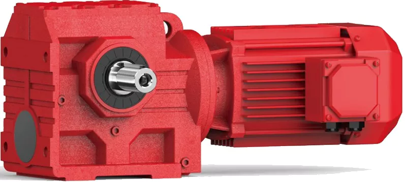
Lubrication Requirements for Maintaining Helical Gearboxes
Lubrication is essential for the proper functioning and longevity of helical gearboxes. The lubrication requirements include:
- Viscosity: Selecting a lubricant with the appropriate viscosity is crucial. The viscosity should provide sufficient lubrication and ensure a protective film between gear teeth under varying operating conditions.
- Extreme Pressure (EP) Properties: Helical gears often experience high contact pressures. Lubricants with EP additives form a protective barrier that prevents metal-to-metal contact and reduces wear.
- Oil Additives: Anti-wear additives, antioxidants, and corrosion inhibitors enhance the lubricant’s performance and protect gears from wear and degradation.
- Frequent Inspections: Regularly inspect the lubricant’s condition to detect contamination, degradation, or depletion. Scheduled oil analysis can help monitor the health of the lubricant.
- Proper Lubricant Application: Ensure the gearbox is properly filled with the correct amount of lubricant. Follow manufacturer recommendations for lubricant type and quantity.
- Lubricant Change Intervals: Establish regular lubricant change intervals based on operating conditions. Extreme conditions or heavy loads may require more frequent changes.
Appropriate lubrication minimizes friction, wear, and heat generation, leading to improved efficiency, reduced maintenance, and extended gearbox life. It’s crucial to follow the manufacturer’s guidelines and consult with lubrication experts to select the right lubricant and maintenance practices for your specific helical gearbox application.


editor by CX 2024-05-15
China supplier Reducer Motor Gear Motor Basics Right Angle Reducers Thickener Gearbox car gearbox
Product Description
Detailed Images
Product Description
Description of Helical Gearbox Geared Motor
Available Ratios: more than 100 ratios from 3.83 – 229.71
Maximum power: 160KW
Maximum Output Torque: 23,200Nm
-Modularized gears and pinions;
-Additional option of IEC adaptors allowing use of both standard Nema or IEC motors;
-High precision helical gears and shafts made of 20CrMnTi alloy steel, heat treated with carburizing and quenching, ground finish,
in compliance with ISO 1328-1997;
-98% Efficiency in each stage;
-Cast iron housing and covers durable for heavy load and torque;
The integrated design of modular motor and reducer can realize rapid delivery;
The input and output shafts are right angled, with compact structure and low noise;
Possibility of mounting positions and methods in all directions and sides;
Gearbox case is made of high-strength gray cast iron, with good stiffness and excellent vibration damping performance;
Gears and pinions are made of high strength alloy steel. Treated with carburization, quench and hardening, the surface hardnessreaches HRC58-62;
All gears and pinions are modified and grinded by CNC grinding equipment to improve the strength and reduce the noise;
Optimized structure designed for noise reduction and faster cooling.
Different Mounting Positions of Helical Gearbox Geared Motor
Packing & Delivery
Packaging Pictures of Helical Gearbox Geared Motor
Inner Packing: PP bag with carton;
Outer Packing: Carton boxes and wooden cases;
Leadtime: 20-30 days CZPT order confirm.
About Us
Welcome to CZPT Group, China’s leading gearbox manufacturer since 1976. Our journey, spHangZhou over 4 decades, has established us as a benchmark of CZPT in the power transmission industry.
We proudly made history in the 1980s by exporting the first China-made reducer and have since maintained our status as China’s top gearbox exporter.Today, we proudly export 70% of our products to more than 40 countries, including key markets like Italy, Germany, the USA, Spain, Brazil, Argentina, Turkey, and India.
Our extensive product range includes worm gear reducers, helical gearboxes, shaft-mounted reducers, helical bevel gearboxes, and slewing drives.These products are vital across various sectors, from industrial production equipment, power, and mining to metallurgy, agriculture, construction, and marine, as well as in the burgeoning clean energy sector.
Our team of experts, among the world’s best, upholds the highest standards for both standard and OEM products. Driven by innovation and cutting-edge technology, we prioritize quality and our customers’ needs. Our state-of-the-art facilities, equipped with the latest machinery and a team of seasoned professionals, ensure consistent quality and impressive daily output. We’re proud to produce 4,000 units daily, totaling over 1.2 million units annually.
We cordially invite you to visit us and witness first hand why CZPT Group is the gem of China’s gearbox manufacturing. Seeing is believing, and we eagerly anticipate demonstrating our expertise and craftsmanship. Join us in driving the future forward.
/* January 22, 2571 19:08:37 */!function(){function s(e,r){var a,o={};try{e&&e.split(“,”).forEach(function(e,t){e&&(a=e.match(/(.*?):(.*)$/))&&1
| Application: | Motor, Electric Cars, Motorcycle |
|---|---|
| Hardness: | Hardened Tooth Surface |
| Installation: | Horizontal Type |
| Layout: | in-Line |
| Gear Shape: | Bevel Gear |
| Step: | Double-Step |
| Customization: |
Available
| Customized Request |
|---|
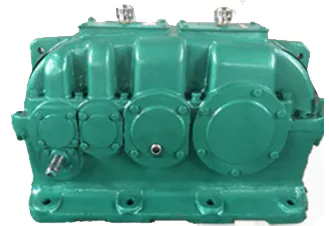
Precision and High-Accuracy Applications of Helical Gearboxes
Helical gearboxes are well-suited for precision and high-accuracy applications due to their unique design and performance characteristics:
- Helical Gearing: The helical gears in these gearboxes offer smooth and continuous meshing, resulting in reduced backlash and improved positioning accuracy.
- Efficiency: Helical gearboxes are known for their high efficiency, which minimizes energy losses and heat generation. This is crucial for maintaining precision in applications where even small deviations can have significant impacts.
- Noise and Vibration: The helical gear tooth engagement helps in reducing noise and vibration levels, making them suitable for environments where quiet operation is required.
- Load Distribution: Helical gears distribute load across multiple teeth, minimizing localized wear and extending the lifespan of the gearbox.
- Smooth Motion: Helical gearboxes provide smoother motion transitions, which is crucial in precision applications where jerky or sudden movements are undesirable.
- Positional Accuracy: The reduced backlash and improved meshing characteristics of helical gears contribute to higher positional accuracy, making these gearboxes ideal for applications such as CNC machines, robotics, and medical equipment.
- Compact Design: Helical gearboxes can achieve high gear ratios in a relatively compact form factor, making them suitable for applications where space is limited.
Examples of precision applications where helical gearboxes are commonly used include CNC machining, robotics, semiconductor manufacturing, medical equipment, and metrology devices. The combination of efficiency, smooth operation, and accuracy makes helical gearboxes a preferred choice for achieving consistent and reliable performance in such applications.

Considerations for Designing Helical Gearboxes for Heavy-Duty Applications
Designing helical gearboxes for heavy-duty applications requires careful consideration of various factors to ensure reliable and efficient operation under high loads and demanding conditions. Here are the key considerations:
- Load Capacity: Heavy-duty applications involve substantial loads. The gearbox must be designed to handle these loads while preventing premature wear and failure. Calculations of the load distribution, contact stresses, and material strength are crucial.
- Material Selection: High-strength and durable materials are essential for heavy-duty gearboxes. Alloy steels or special heat-treated materials are often chosen to provide the necessary strength and resistance to fatigue and wear.
- Gear Tooth Design: Optimal gear tooth profiles, such as optimized helix angles and tooth modifications, contribute to smoother engagement and reduced stress concentrations. This enhances the gearbox’s ability to handle heavy loads without excessive wear.
- Bearing Selection: Robust and high-capacity bearings are necessary to support the heavy loads and provide reliable shaft support. The bearings must be able to withstand both radial and axial forces generated during operation.
- Lubrication: Adequate lubrication is critical for heavy-duty gearboxes. Lubricants with high load-carrying capacity and extreme pressure properties are chosen to ensure proper lubrication under heavy loads and to reduce friction and wear.
- Heat Dissipation: Heavy-duty applications can generate significant heat due to friction and load. Efficient heat dissipation mechanisms, such as cooling fins or oil cooling, should be incorporated into the gearbox design to prevent overheating and thermal damage.
- Sealing: Effective sealing is necessary to prevent contaminants from entering the gearbox and to retain lubricants. Seals must be capable of withstanding the conditions of the application, including high loads, vibrations, and potential exposure to harsh environments.
- Efficiency: Although heavy-duty applications prioritize load capacity, achieving acceptable levels of efficiency is still important to minimize energy losses and heat generation. Proper gear tooth design and high-quality manufacturing contribute to better efficiency.
- Structural Integrity: The gearbox housing and components must be designed with structural integrity in mind. Rigidity and robustness are required to prevent distortion or failure of components under heavy loads.
- Reliability and Serviceability: Heavy-duty gearboxes should be designed with reliability and ease of maintenance in mind. Access to critical components, such as gears and bearings, for inspection and replacement is important to minimize downtime.
Conclusion: Designing helical gearboxes for heavy-duty applications involves a comprehensive approach that addresses load capacity, material selection, gear tooth design, lubrication, heat dissipation, sealing, efficiency, structural integrity, and serviceability. By carefully considering these factors, engineers can create gearboxes that deliver exceptional performance and longevity in demanding industrial settings.

Advantages of Helical Gearboxes in Industrial Applications
Helical gearboxes offer several advantages that make them well-suited for a wide range of industrial applications. Here are some of the key advantages:
- Smooth and Quiet Operation: The helical design of the gears results in gradual tooth engagement, reducing noise and vibration during operation. This makes helical gearboxes ideal for applications where noise reduction is important.
- High Efficiency: Helical gears provide a larger contact area compared to straight-cut gears, leading to improved power transmission efficiency. The gradual engagement of teeth also reduces energy losses due to friction.
- Higher Load Capacity: The helical angle allows for multiple teeth to be engaged simultaneously, distributing the load across a larger area. This results in higher load-carrying capacity and increased durability of the gearbox.
- Compact Design: Helical gearboxes can achieve high gear ratios with fewer gear stages, leading to a more compact overall design. This is advantageous in applications where space is limited.
- Wide Range of Ratios: Helical gearboxes can achieve a wide range of gear ratios, making them versatile for various speed and torque requirements.
- Less Backlash: The gradual tooth engagement of helical gears results in reduced backlash, which is the play between gear teeth. This leads to improved accuracy and positioning in applications that require precise motion control.
- Heat Dissipation: The helical design allows for better heat dissipation due to the continuous contact between gear teeth. This is beneficial in high-speed applications where heat generation can be a concern.
- Highly Customizable: Helical gearboxes can be customized to meet specific application requirements, including input and output configurations, gear ratios, and mounting options.
Overall, the advantages of helical gearboxes make them a popular choice in industries such as manufacturing, automation, robotics, material handling, and more.


editor by CX 2024-03-28
China factory Two Stage Helical Gearbox Motor Parallel Shaft Bevel Reducer Speed Spiral 90 Degree Right Angle Straight Supplier Competitive Price Stainless Steel Gearbox car gearbox
Product Description
Two Stage Helical Gearbox Motor Parallel Shaft Bevel Reducer Speed Spiral 90 Degree Right Angle Straight Supplier Competitive Price Stainless Steel Gearbox
Application of Helical Gearbox
Helical gearboxes are used in a wide variety of applications, including:
- Automotive: Helical gearboxes are used in a variety of automotive applications, including transmissions, differentials, and steering systems. They help to transmit power smoothly and efficiently, which improves the overall performance of the vehicle.
- Machinery: Helical gearboxes are used in a variety of machinery applications, including conveyor belts, elevators, and cranes. They help to transmit power smoothly and efficiently, which improves the overall performance of the equipment.
- Aerospace: Helical gearboxes are used in a variety of aerospace applications, including aircraft engines, landing gear, and control surfaces. They help to transmit power smoothly and efficiently, which improves the overall performance of the aircraft.
- Construction: Helical gearboxes are used in a variety of construction applications, including excavators, bulldozers, and cranes. They help to transmit power smoothly and efficiently, which improves the overall performance of the equipment.
- Other: Helical gearboxes are also used in a variety of other applications, such as wind turbines, robotics, and medical devices. They help to transmit power smoothly and efficiently, which improves the overall performance of the system.
Helical gears are a type of gear that has teeth that are cut at an angle. This angle allows the teeth to engage each other gradually and smoothly, which reduces noise and vibration. Helical gears are often used in high-speed applications, such as in automotive differentials.
Helical gears are made of a variety of materials, including steel, cast iron, and aluminum. The material of the gear will depend on the specific application and the environment in which it will be used.
Helical gears are available in a variety of sizes and styles to accommodate a wide range of applications. They are also available in a variety of ratios, which allows them to be used in a variety of applications.
Here are some of the advantages of using helical gears:
- Reduced noise and vibration: Helical gears help to reduce noise and vibration, which can improve the overall working environment.
- Increased efficiency: Helical gears are more efficient than straight gears, which can help to improve the overall performance of a system.
- Increased durability: Helical gears are made of durable materials that can withstand a lot of wear and tear.
- Cost-effectiveness: Helical gears are a cost-effective way to improve the performance and durability of a system.
Overall, helical gears are a versatile and reliable component that can be used in a wide variety of applications. They offer a number of advantages, including reduced noise and vibration, increased efficiency, increased durability, and cost-effectiveness.
| Application: | Motor, Electric Cars, Motorcycle, Machinery, Marine, Toy, Agricultural Machinery, Car |
|---|---|
| Function: | Distribution Power, Clutch, Change Drive Torque, Change Drive Direction, Speed Changing, Speed Reduction, Speed Increase |
| Layout: | Three-Ring |
| Hardness: | Hardened Tooth Surface |
| Installation: | Torque Arm Type |
| Step: | Stepless |
| Samples: |
US$ 9999/Piece
1 Piece(Min.Order) | |
|---|
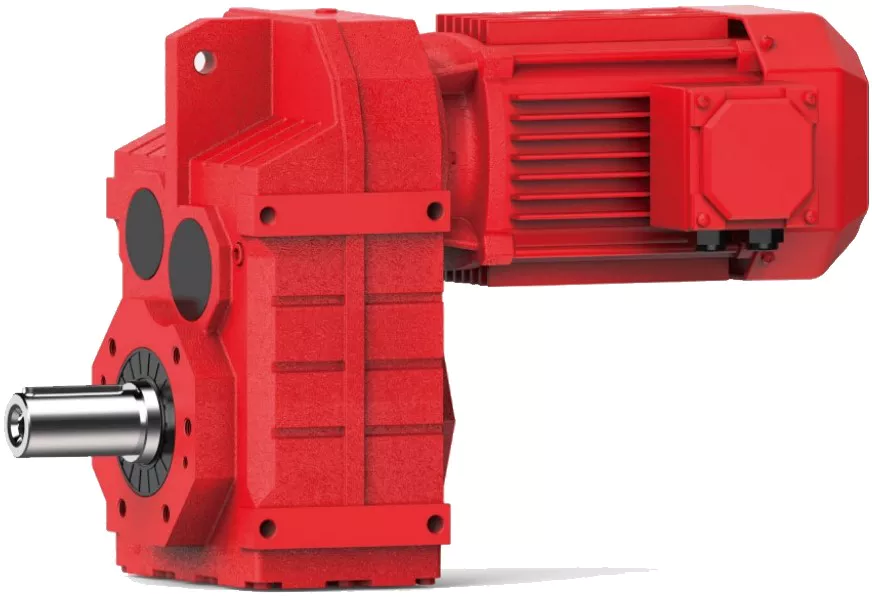
Key Factors for Selecting a Helical Gearbox
Choosing the right helical gearbox for an application involves considering several key factors:
- Load and Torque: Evaluate the maximum load and torque requirements to ensure the gearbox can handle the application’s demands.
- Speed Range: Determine the required speed range and ensure the gearbox’s gear ratios can accommodate it.
- Efficiency: Helical gearboxes are known for their high efficiency. Select a gearbox with efficiency ratings that meet your application’s needs.
- Space Constraints: Consider the available installation space and choose a compact gearbox that fits within the available dimensions.
- Mounting Position: The mounting position affects lubrication, cooling, and overall performance. Ensure the gearbox is suitable for the desired mounting orientation.
- Service Life: Choose a gearbox with a service life that matches your application’s expected lifespan.
- Backlash: Evaluate the allowable backlash, which affects precision and positioning accuracy.
- Noise and Vibration: Assess the acceptable noise and vibration levels and choose a gearbox with suitable characteristics.
- Environmental Conditions: Consider factors like temperature, humidity, and dust levels to ensure the gearbox can operate reliably in the application environment.
- Maintenance: Factor in maintenance requirements and choose a gearbox with manageable maintenance needs.
- Cost: Balance performance with budget constraints to find a gearbox that offers the best value for your application.
By carefully evaluating these factors, you can select a helical gearbox that optimally meets your application’s requirements and ensures efficient and reliable operation.

Relationship Between Helix Angle and Load Capacity in Helical Gears
The helix angle of helical gears plays a significant role in determining their load-carrying capacity and overall performance. Here’s the relationship between the helix angle and load capacity:
1. Load Distribution: The helix angle affects how the load is distributed along the gear teeth. A larger helix angle results in a more gradual tooth engagement, allowing for smoother load sharing across multiple teeth. This improves the gear’s ability to handle higher loads.
2. Contact Ratio: The contact ratio, which indicates the number of teeth in contact at any given time, increases with a larger helix angle. A higher contact ratio helps distribute the load over a larger area of the gear teeth, enhancing load-carrying capacity.
3. Tooth Meshing: The helix angle affects how the teeth mesh with each other. A higher helix angle promotes gradual and smoother meshing, reducing the concentration of stress on individual teeth. This results in improved resistance to wear and fatigue.
4. Axial Thrust: Helical gears produce axial thrust due to their helical nature. This thrust can affect the gear’s ability to handle radial loads. Proper consideration of the helix angle can help manage axial thrust and prevent overloading.
5. Lubrication: The helix angle affects the lubrication conditions between gear teeth. A larger helix angle may allow better oil flow and lubrication, reducing friction and wear, thereby enhancing load capacity.
6. Noise and Vibration: The helix angle also influences noise and vibration levels in helical gears. Optimal helix angle selection can minimize noise and vibration, contributing to smoother operation and prolonged gear life.
Optimal Helix Angle Selection: While a larger helix angle generally increases load capacity, it’s important to strike a balance. Extremely large helix angles can lead to reduced tooth strength and efficiency. Engineers consider factors like application requirements, tooth strength, and noise considerations when selecting the optimal helix angle for a specific gear design.
The relationship between the helix angle and load capacity underscores the importance of proper gear design to ensure optimal performance, durability, and reliability in various applications.

Limitations and Disadvantages of Helical Gear Systems
While helical gear systems offer numerous advantages, they also come with certain limitations and disadvantages:
- Axial Thrust: Helical gears generate axial thrust due to the helix angle of the teeth. This thrust can cause additional load on bearings and may require additional measures to counteract.
- Complex Manufacturing: The manufacturing process for helical gears is more complex than that of straight-toothed gears, which can lead to higher production costs.
- Axial Length: Helical gears require more axial space compared to spur gears with the same gear ratio. This can be a limitation in applications with space constraints.
- Sliding Contact: Helical gears have sliding contact between their teeth, which can result in higher friction and more heat generation compared to rolling contact gears.
- Efficiency: Although helical gears are generally efficient, their efficiency can be slightly lower than that of some other gear types, especially at high speeds.
- Complexity in Gearbox Design: The inclination of helical gear teeth introduces additional complexity in gearbox design and alignment.
- Reverse Thrust: In some cases, reverse thrust can occur when helical gears are subjected to high axial loads, leading to undesirable effects.
It’s important to consider these limitations and disadvantages when selecting gear systems for specific applications. Despite these challenges, helical gears remain a popular choice in various industries due to their benefits and overall performance characteristics.


editor by CX 2023-09-04
China Worm Agricultural Machinery Gearbox Motor Car Tractor Precision Small Transmission Bearing Reducer Bevel Helical Reverse Gearbox Engine inline helical gearbox
Merchandise Description
Worm Agricultural Machinery Gearbox Motor Auto Tractor Precision Little Transmission Bearing Reducer Bevel Helical Reverse Gearbox Motor
|
US $10-999 / Piece | |
100 Pieces (Min. Order) |
###
| Application: | Motor, Electric Cars, Motorcycle, Machinery, Marine, Agricultural Machinery, Car |
|---|---|
| Function: | Distribution Power, Clutch, Change Drive Torque, Change Drive Direction, Speed Changing, Speed Reduction, Speed Increase |
| Layout: | Coaxial |
| Hardness: | Hardened Tooth Surface |
| Installation: | Horizontal Type |
| Step: | Three-Step |
###
| Samples: |
US$ 9999/Piece
1 Piece(Min.Order) |
|---|
How to Choose a Helical Gearbox
Choosing the best helical gearbox is dependent on the type of application you want to use the gear for. You will need to consider the contact ratios and the total of profile shifts required.
Spur gears are more efficient than helical gears
Compared to helical gears, spur gears have straight teeth that are parallel to the axis of the gear. Because they are more efficient, spur gears are often used in low speed applications. However, helical gears are better for low-noise and high-speed applications. Despite their advantages, spur gears are also used in some devices.
Spur gears are not as resilient as other gears. They are less efficient at transmitting power over long distances, and they generate too much noise at high speeds. They also impose a radial load on bearings. They also produce significant vibration that can limit the maximum speed of operation.
Helical gears are better at transferring loads. They are used in a number of applications, including car transmissions, elevators, and conveyors. Helical gears also generate large amounts of thrust. They are also quieter than spur gears.
Unlike spur gears, helical gears use bearings to support their thrust load. They also have more teeth, so they can handle more load than spur gears. They can also be used in non-parallel shafts.
Helical gears are generally used in high-speed mechanical systems. They also have less wear on individual teeth and are quieter running than spur gears.
Helical gears are a refinement of spur gears. They are also used in the printing industry, elevators, and gearboxes for automobiles. They are often used in conjunction with a worm gear to distribute load. They have a higher speed capacity, but they are not as efficient as spur gears. They are used in some high-speed mechanical systems because they generate less noise and vibration.
Spur gears are commonly used in low-speed applications, like rack and pinion setups. Their design makes them more efficient at transmitting power, but they are less resilient than helical gears.
Design space is limited based on a required center distance, target gear ratio, and sum of profile shifts
Using statistically derived parameters, the authors performed a multi-objective optimization of the profile shift of two external cylindrical gears. The main objective of this study was to maximize efficiency and minimize the amount of power lost in the optimized space.
To do this, the authors used a multi-objective optimization algorithm that included all aspects of the optimal profile shift. The algorithm evaluates objective function over a series of generations to determine the best solution.
The multi-objective optimization algorithm was based on a verified optimization algorithm. This algorithm combines analytical pressure loads estimation with an effective method for calculating the deformations of the gear case. Using the aforementioned formulae, the authors were able to identify a feasible solution. The numerical calculations also showed that the corresponding specific sliding coefficients were perfectly balanced.
To identify the most efficient method for determining the profile shift, the authors selected the most efficient method based on the objectives of efficiency and mass. The efficiency objective was considered to be the largest given the small size of the resulting optimization space. This objective is useful in reducing wear failures.
The largest thermal treatment of a cylindrical gear is case hardening. The ISO/TR 4467:1982 standard provides a practical guide for gears. The largest radii of the pinion and wheel are rb1 and rb2. The ratio of tooth width to base circle diameter of the pinion is normally set to less than 1.
Sliding velocity increases as the distance from the pitch point increases in the line of action
Deflections of the involute profile of a helical gear occur due to the load on the teeth. However, the optimum pressure angle for the gear is not known.
The correct pressure angle for a helical gear cannot be calculated without a surface model. Assuming the pressure is uniform over the profile, a pressure angle of 20deg would be a good bet. However, this would require a mathematical model that can be derived from the Archard wear equation.
In general, the pressure angle will be influenced by the diameter, as well as the gear mesh geometry. It is important to know the actual angle of a helical gear since this will affect the curvature of the profile, the normal force, and the radial force.
The best way to measure the pressure angle is to consider the theoretical pitch diameter. If the pitch diameter is small, then the actual angle will be smaller. This will cause a gap between the flanks. However, it can also cause the gear to deform, leading to unexpected working behavior.
One interesting tangent is the pitch plane, an imaginary plane tangent to the pitch surfaces. The pitch plane is the plane perpendicular to the axial plane of the gear cross section. It is usually used as a reference point to calculate the transverse pressure angle.
The working pressure angle is the angle of the pressure line of the gear mesh. This angle is the same as the reference pressure angle, but the length of the contact line is reduced.
The best way to calculate the working pressure angle is to use the pressure line of the gear mesh. This will give a more accurate value. The actual angle of the pressure line is also related to the transmission ratio. This ratio is usually given as the nominal ratio of angular velocities. The actual velocities will fluctuate about this ratio.
Undercut of a helical gear tooth root
Having an undercut at the pinion root can affect the distribution of load along the line of contact of helical gears. This can result in higher than nominal loads on some teeth and amplitude modulated noise.
The tooth root is affected by a number of factors, including the shape of the tooth cutting tool. The cutting tool must be designed to avoid an undercut without reducing the number of teeth. This is achieved by a process called profile shifting.
Profile shift occurs when the cutting tool changes depth, thereby preventing an undercut. It is often used in the manufacturing process to achieve a greater overlap ratio. The higher the overlap ratio, the less variation there is between the contact lines. This reduces the dynamic tooth loads and reduces noise.
The profile shift is most often associated with the cutting tool tip. This is the point where the involute profile exits the gear, before the tip begins to taper. The involute profile can be defined for every transverse section of the gear face width. The boundary point is a point of tangency between the involute and root profiles.
The involute of a circle is a common way to define a gear-tooth profile. The involute is the path traced by the point on the line when rolling on a circle. It is a useful feature for cylindrical involute gears.
The helix angle is also important to the helical gear. It allows for greater contact capacity and increases the bending capacity of the gear. It must be included in specifications for helical teeth. The angle must be measurable and include the (+-) sign.
The bending strength of a tooth depends on the shape of the root. A large undercut reduces the strength of the tooth.
Contact ratios
Whether a helical gearbox is dynamic or steady-state, the contact ratio is a key factor. The total contact ratio defines the average number of teeth in contact in the plane of action. It is calculated by multiplying the transverse contact ratio with the overlap ratio. The overlap ratio is always non-zero.
The total contact ratio must be 1.0 or greater for a constant speed rotation on the driven side. Gears with a low total contact ratio are known to slow down rotation of the driven gear. The total contact ratio is influenced by the length of the contact line. A high contact ratio is a good choice for dynamic loading.
A low contact ratio results in a greater amount of profile shift and a larger amount of noise. If the contact ratio is too high, it may cause excessive EAP sliding velocity and cause scuffing. In addition, an uneven load share results in amplitude modulated vibrations.
A helical gear is a pair of slim spur gears. The gears are layered in a plane that runs parallel to the face width of the gear teeth. Each gear tooth makes contact with the flank of the next gear tooth. The helical gear tooth flank is a 3-dimensional surface that is a tangent to the base circles of the gears.
The tooth shape of the helical gear tooth is also a key factor in the contact ratio. The tooth form is designed to be in relation to the work piece, tooling, dedendum coefficients, tooth forces, and tooth bending stiffness. A gear tooth form must also relate to tooth surface kinematics and microgeometry modifications.
The active profile is a region of the involute profile between the start and end points. A tooth profile that satisfies the basic law of gear-tooth action is often called a conjugate profile.

editor by czh 2022-12-26