Product Description
G3 series helical geared motor,
1. Two types of housing: Aluminum alloy and cast iron; Two kinds of frames: foot mounting and flange mounting. They are good-looking in appearance, suitable for universal mounting.
2. Helical gear with the high-10sile alloy material makes the construction more compact, housing smaller, efficiency higher, output torque larger.
3.Hardened facing & well finished transmission gear has the advantages : seldom distortion, high precision,stable transmission, lower noise, possible for continuous work under the dreadful conditions.
4.With 6 specification for the diameter of output shaft: Ø18,Ø22,Ø28,Ø32,Ø40,Ø50.
5.Two or three-stage transmission, large in ratio range, each single frame size with 14 ratios from 5:1 to 200:1.
6.Using high quality bearing prolongs the use life.
7.High-performance oil seal prevents the lubricant from leaki
ng back to the inner of motor.
8.Three-phase motor combined the standard and full-enclosed aluminum motor, which is good in waterproof, easy in heat dissipation, high in running efficiency.
9.Modular combination extends the transmission ratio from i=5:1 to 1400:1.
| Power kw | Output shaft | Ratio | Primary outline and dimension-mount | |||||||||||||||||
| A | F | I | J | M | O | O1 | P | Q | R | S | T | U | W | X | Y | Y1 | ||||
| 1 | 2 | |||||||||||||||||||
| 0.2 | 18 | 5/10/15/20/25 | 267 | 270 | 192.5 | 11 | 16.5 | 170 | 4 | 10 | 30 | 145 | 35 | 18 | 20.5 | 129 | 6 | 161 | 80 | 81 |
| 22 | 30/40 50/60 80/100 | 293 | 296 | 197.5 | 11 | 19 | 185 | 4 | 12 | 40 | 148 | 47 | 22 | 24.5 | 129 | 6 | 171.5 | 89.5 | 83.5 | |
| 28 | 100/120 160/200 | 306 | 309.5 | 208.5 | 11 | 23.5 | 215 | 4 | 15 | 45 | 170 | 50 | 28 | 31 | 129 | 8 | 198.5 | 105.5 | 88 | |
/* January 22, 2571 19:08:37 */!function(){function s(e,r){var a,o={};try{e&&e.split(“,”).forEach(function(e,t){e&&(a=e.match(/(.*?):(.*)$/))&&1
| Output Speed: | 14-280rpm |
|---|---|
| Input Speed: | 1400rpm |
| Power: | 0.1kw-2.2kw |
| Color: | Silver White |
| Speed Ratio: | 5/10/15/20/25/30/40/50 |
| Transport Package: | 1 Set / Carton, Several Cartons / Wooden Pallet |
| Customization: |
Available
| Customized Request |
|---|
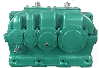
Precision and High-Accuracy Applications of Helical Gearboxes
Helical gearboxes are well-suited for precision and high-accuracy applications due to their unique design and performance characteristics:
- Helical Gearing: The helical gears in these gearboxes offer smooth and continuous meshing, resulting in reduced backlash and improved positioning accuracy.
- Efficiency: Helical gearboxes are known for their high efficiency, which minimizes energy losses and heat generation. This is crucial for maintaining precision in applications where even small deviations can have significant impacts.
- Noise and Vibration: The helical gear tooth engagement helps in reducing noise and vibration levels, making them suitable for environments where quiet operation is required.
- Load Distribution: Helical gears distribute load across multiple teeth, minimizing localized wear and extending the lifespan of the gearbox.
- Smooth Motion: Helical gearboxes provide smoother motion transitions, which is crucial in precision applications where jerky or sudden movements are undesirable.
- Positional Accuracy: The reduced backlash and improved meshing characteristics of helical gears contribute to higher positional accuracy, making these gearboxes ideal for applications such as CNC machines, robotics, and medical equipment.
- Compact Design: Helical gearboxes can achieve high gear ratios in a relatively compact form factor, making them suitable for applications where space is limited.
Examples of precision applications where helical gearboxes are commonly used include CNC machining, robotics, semiconductor manufacturing, medical equipment, and metrology devices. The combination of efficiency, smooth operation, and accuracy makes helical gearboxes a preferred choice for achieving consistent and reliable performance in such applications.
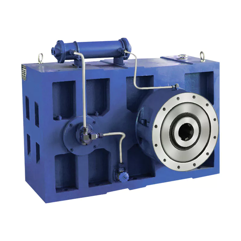
Troubleshooting Common Issues in Helical Gear Systems
Troubleshooting helical gear systems involves identifying and addressing common issues that can affect their performance. Here’s a step-by-step process:
- Visual Inspection: Begin by visually inspecting the gearbox for any signs of wear, damage, or misalignment. Look for worn or chipped gear teeth, oil leakage, and unusual noise.
- Noise Analysis: If noise is present, analyze its type and frequency. Whining or grinding noises could indicate misalignment or damaged gears, while clicking or knocking sounds might point to loose components.
- Lubrication Check: Ensure that the gearbox is properly lubricated with the recommended type and quantity of lubricant. Insufficient lubrication can lead to increased friction and wear.
- Alignment Check: Check the alignment of the gears and shafts. Misalignment can result in uneven wear, noise, and reduced efficiency. Realign components if necessary.
- Gear Inspection: Inspect gear teeth for signs of pitting, scoring, or wear. Replace any damaged gears to prevent further issues.
- Bearing Examination: Check the condition of bearings that support shafts and gears. Worn or damaged bearings can lead to increased vibration and noise.
- Tightening and Fastening: Ensure that all bolts, fasteners, and connections are properly tightened. Loose components can cause vibrations and noise.
- Load Analysis: Evaluate the load conditions and operating parameters of the gearbox. Ensure that the gearbox is not subjected to loads beyond its design capacity.
- Temperature Monitoring: Monitor the operating temperature of the gearbox. Excessive heat can indicate problems such as inadequate lubrication or overloading.
- Consulting Experts: If issues persist or if you’re unsure about the diagnosis and solution, consult gearbox experts or manufacturers for guidance.
By following this troubleshooting process, you can identify and resolve common issues in helical gear systems, ensuring optimal performance and longevity.
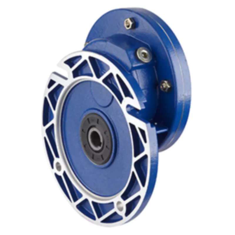
Handling High Torque and Heavy Loads in Helical Gearboxes
Helical gearboxes are well-suited for handling high torque and heavy loads due to their unique design and meshing characteristics:
- Helical Teeth: The helical shape of the gear teeth allows for gradual and continuous contact between the teeth during meshing. This results in smoother load distribution and reduced impact forces, making helical gears capable of handling heavy loads.
- Multiple Tooth Contact: Helical gears have multiple teeth in contact at any given time, spreading the load over a larger area of gear teeth. This helps to distribute the load evenly and prevent localized wear and stress concentrations.
- Increased Tooth Strength: The inclined orientation of helical gear teeth increases the tooth width, leading to greater tooth strength and improved load-carrying capacity.
- Bearings and Shaft Design: The gearbox housing is designed to support heavy loads and provide proper alignment for the shafts and bearings. High-quality bearings and shafts help distribute the load and reduce wear.
- Lubrication: Adequate lubrication is crucial to minimize friction and heat generation between gear teeth. Proper lubrication also helps to dissipate heat generated by the heavy loads.
- Material Selection: High-strength materials with good wear resistance properties are chosen for helical gears to ensure they can withstand the demands of heavy loads.
Overall, the gradual engagement of helical gear teeth and their ability to handle multiple tooth contact positions them as a reliable choice for applications that require high torque and can handle heavy loads. Engineers carefully design helical gearboxes to ensure they can withstand the stresses imposed by the application’s specific requirements.


editor by CX 2024-04-29
China OEM Pre-Stage PC080 Helical Gearbox Unit Helical Geared Motors supplier
Product Description
Features:
1.Made of high quality aluminium alloy gear reducer,die-cast,non-rusting,convenient to be mounted with worm gearboxes & motors as as to achieve the required speed ratio.
2.Fitting the pre-stage helical module on the main reduction unit is easily done as for any motor of type B14.
3.The PC construction is modular and therefore it can be as a separte unit mounted on any type of fitted geared motor(PAM).
Technical data:
1.Four types manufactured:PC063,PC071,PC080,PC090
2.Speed ratio range:1:2.43—1:3
3.Model: PC063/PC071/PC080/PC090
Quality control
(1) Quality guarantee: 1 year
(2) Certificate of quality: ISO9001,CCC and CE
(3) Every product must be tested before sending
Technical performance and selection reference
| Model | P | D | D* | P1 |
| PC063 | 105 | 11 | 14 | 140(63B5) |
| PC071 | 120 | 14 | 19 | 160(71B5) |
| PC080 | 160 | 19 | 24/28 | 200(80B5) |
| PC090 | 160 | 24 | 19/28 | 200(90B5) |
Note recommendations
To install the reduction unit it is necessary tonote the following recommendations:
1. Check the correct direction of rotation of thereduction unit output shaft before fitting the unit tothe machine.
2. Before mount with the prime moveanddevice,please check the reducers every axiadiameter, aperture,key and key slot,
to be theirdimensions are not deviation, and avoidassembaurtoo tight or too loose, unless it wilinfluence the reducer’s performance.
3. The mounting on the machine must be stableto avoid anv vibration.
4.Whenever possible,protect the reductiorunit against solar radiation and bad weather.
5.In the case of particularly lengthy periods ofstorage (4-6 months), if the oil seal is not immersedin the lubricant inside the unit.
It is recommended tochange it since the rubber could stick to the shaft ormay even have lost the elasticity it needs to functionproperly.
6.Painting must definitely not go over rubberparts and the holes on the breather plugs, if any.
7.When connect with hollow or CZPT shaftplease grease the joint to avoid lock or oxidation.
8.Check the correct level of the lubricantthrough the indicator, if there is one.
9. Starting must take place gradually, withoutimmediately applying the maximum load
10. Supporting unit is required when usingvarious of reducer matched with motor directiy andthe wsight of motor is a little bigger than common.
11 .Ensure the motor cools correctly byassuring good passage of air from the fan side.
12. In the case of ambient temperatures+40°C call the Technical Service.
/* January 22, 2571 19:08:37 */!function(){function s(e,r){var a,o={};try{e&&e.split(“,”).forEach(function(e,t){e&&(a=e.match(/(.*?):(.*)$/))&&1
| Application: | Motor, Electric Cars, Motorcycle, Machinery, Marine, Toy, Agricultural Machinery, Car |
|---|---|
| Function: | Distribution Power, Clutch, Change Drive Torque, Change Drive Direction, Speed Changing, Speed Reduction, Speed Increase |
| Layout: | Cycloidal |
| Samples: |
US$ 59/Piece
1 Piece(Min.Order) | Order Sample |
|---|
| Customization: |
Available
| Customized Request |
|---|
.shipping-cost-tm .tm-status-off{background: none;padding:0;color: #1470cc}
|
Shipping Cost:
Estimated freight per unit. |
about shipping cost and estimated delivery time. |
|---|
| Payment Method: |
|
|---|---|
|
Initial Payment Full Payment |
| Currency: | US$ |
|---|
| Return&refunds: | You can apply for a refund up to 30 days after receipt of the products. |
|---|
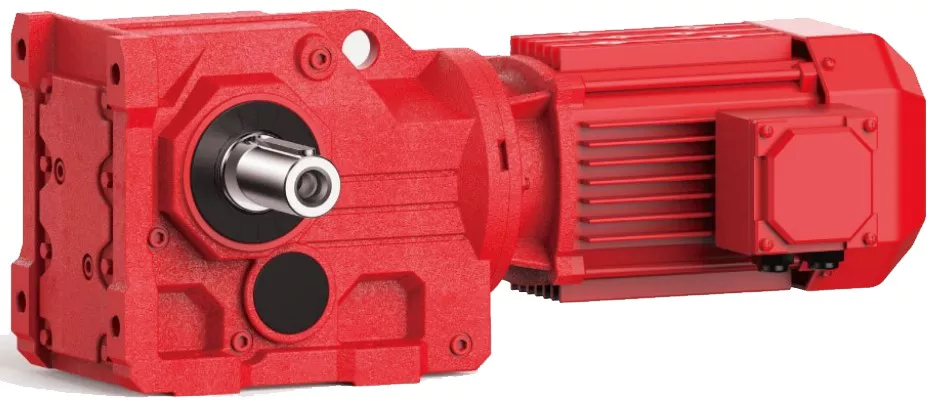
Using Helical Gearboxes for Speed Reduction and Speed Increase
Yes, helical gearboxes can be used for both speed reduction and speed increase in various applications. The design of helical gears allows them to transmit motion and power between non-parallel shafts while changing the rotational speed.
Speed Reduction: When the driving gear (pinion) has fewer teeth than the driven gear, the gear ratio leads to speed reduction. This is commonly used in applications where the input speed needs to be decreased while increasing the output torque. For example, helical gearboxes are often employed in conveyor systems to reduce the speed of the motor while maintaining sufficient torque to move heavy loads.
Speed Increase: Helical gearboxes can also achieve speed increase by having the driving gear (pinion) with more teeth than the driven gear. This configuration is less common but can be used to increase the output speed while sacrificing some torque. Speed increase applications are typically seen in scenarios where higher speeds are required, such as in certain types of machinery or industrial processes.
It’s important to note that while helical gearboxes can perform both speed reduction and speed increase, the specific gear ratios and configurations need to be carefully chosen to ensure efficient and reliable operation for the intended application.

Considerations for Designing Helical Gearboxes for Heavy-Duty Applications
Designing helical gearboxes for heavy-duty applications requires careful consideration of various factors to ensure reliable and efficient operation under high loads and demanding conditions. Here are the key considerations:
- Load Capacity: Heavy-duty applications involve substantial loads. The gearbox must be designed to handle these loads while preventing premature wear and failure. Calculations of the load distribution, contact stresses, and material strength are crucial.
- Material Selection: High-strength and durable materials are essential for heavy-duty gearboxes. Alloy steels or special heat-treated materials are often chosen to provide the necessary strength and resistance to fatigue and wear.
- Gear Tooth Design: Optimal gear tooth profiles, such as optimized helix angles and tooth modifications, contribute to smoother engagement and reduced stress concentrations. This enhances the gearbox’s ability to handle heavy loads without excessive wear.
- Bearing Selection: Robust and high-capacity bearings are necessary to support the heavy loads and provide reliable shaft support. The bearings must be able to withstand both radial and axial forces generated during operation.
- Lubrication: Adequate lubrication is critical for heavy-duty gearboxes. Lubricants with high load-carrying capacity and extreme pressure properties are chosen to ensure proper lubrication under heavy loads and to reduce friction and wear.
- Heat Dissipation: Heavy-duty applications can generate significant heat due to friction and load. Efficient heat dissipation mechanisms, such as cooling fins or oil cooling, should be incorporated into the gearbox design to prevent overheating and thermal damage.
- Sealing: Effective sealing is necessary to prevent contaminants from entering the gearbox and to retain lubricants. Seals must be capable of withstanding the conditions of the application, including high loads, vibrations, and potential exposure to harsh environments.
- Efficiency: Although heavy-duty applications prioritize load capacity, achieving acceptable levels of efficiency is still important to minimize energy losses and heat generation. Proper gear tooth design and high-quality manufacturing contribute to better efficiency.
- Structural Integrity: The gearbox housing and components must be designed with structural integrity in mind. Rigidity and robustness are required to prevent distortion or failure of components under heavy loads.
- Reliability and Serviceability: Heavy-duty gearboxes should be designed with reliability and ease of maintenance in mind. Access to critical components, such as gears and bearings, for inspection and replacement is important to minimize downtime.
Conclusion: Designing helical gearboxes for heavy-duty applications involves a comprehensive approach that addresses load capacity, material selection, gear tooth design, lubrication, heat dissipation, sealing, efficiency, structural integrity, and serviceability. By carefully considering these factors, engineers can create gearboxes that deliver exceptional performance and longevity in demanding industrial settings.
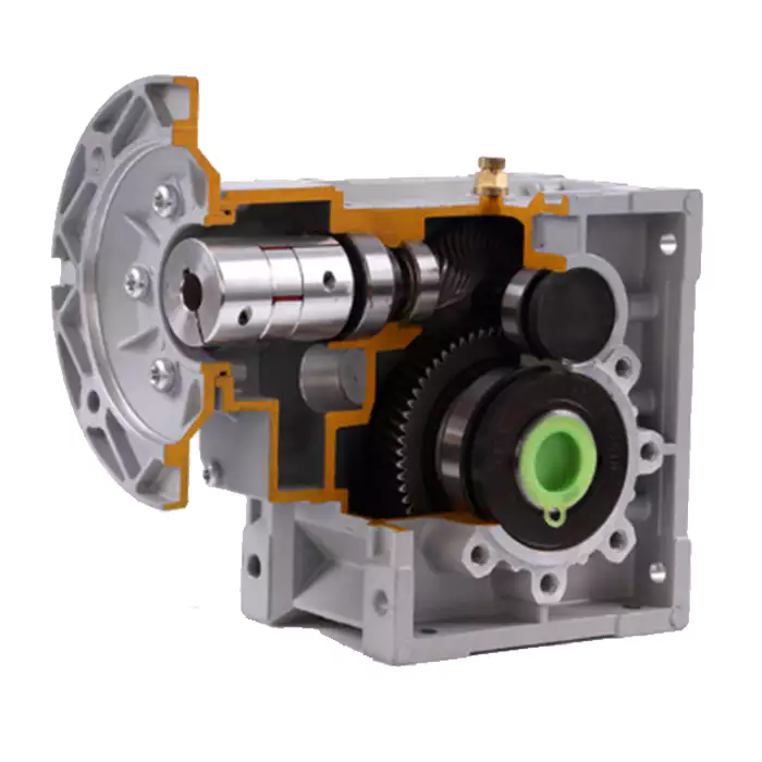
Advantages of Helical Gearboxes in Industrial Applications
Helical gearboxes offer several advantages that make them well-suited for a wide range of industrial applications. Here are some of the key advantages:
- Smooth and Quiet Operation: The helical design of the gears results in gradual tooth engagement, reducing noise and vibration during operation. This makes helical gearboxes ideal for applications where noise reduction is important.
- High Efficiency: Helical gears provide a larger contact area compared to straight-cut gears, leading to improved power transmission efficiency. The gradual engagement of teeth also reduces energy losses due to friction.
- Higher Load Capacity: The helical angle allows for multiple teeth to be engaged simultaneously, distributing the load across a larger area. This results in higher load-carrying capacity and increased durability of the gearbox.
- Compact Design: Helical gearboxes can achieve high gear ratios with fewer gear stages, leading to a more compact overall design. This is advantageous in applications where space is limited.
- Wide Range of Ratios: Helical gearboxes can achieve a wide range of gear ratios, making them versatile for various speed and torque requirements.
- Less Backlash: The gradual tooth engagement of helical gears results in reduced backlash, which is the play between gear teeth. This leads to improved accuracy and positioning in applications that require precise motion control.
- Heat Dissipation: The helical design allows for better heat dissipation due to the continuous contact between gear teeth. This is beneficial in high-speed applications where heat generation can be a concern.
- Highly Customizable: Helical gearboxes can be customized to meet specific application requirements, including input and output configurations, gear ratios, and mounting options.
Overall, the advantages of helical gearboxes make them a popular choice in industries such as manufacturing, automation, robotics, material handling, and more.


editor by CX 2024-04-16
China Standard Speed Reducer Gear Motors Geared Motor Gearbox Gear Unit with Input Flange Roller Press Planetary Worm Helicalgear Reducer Gearbox China Industrial Manufacturer with high quality
Product Description
Speed Reducer Gear Motors Geared Motor Gearbox Gear Unit with Input Flange roller press planetary worm helicalgear reducer gearbox China Industrial Manufacturer
Application of Motor Gearbox
Motor gearboxes are used in a wide variety of applications, including:
- Machine tools. Motor gearboxes are used in machine tools to control the speed of the cutting tool. This allows for the precise machining of materials.
- Conveyors. Motor gearboxes are used in conveyors to control the speed of the conveyor belt. This allows for the efficient and safe transportation of materials.
- Wind turbines. Motor gearboxes are used in wind turbines to control the speed of the turbine blades. This allows for the efficient generation of electricity.
- Elevators. Motor gearboxes are used in elevators to control the speed of the elevator car. This allows for the safe and efficient transportation of people and goods.
- Other applications. Motor gearboxes are also used in a variety of other applications, such as:
- Robotics
- Pumps
- Fans
- Compressors
Motor gearboxes are a critical component in many machines and systems. They allow for the efficient and reliable transmission of power, which is essential for many applications.
Here are some of the advantages of using motor gearboxes:
- Efficiency. Motor gearboxes are very efficient at transmitting power. This is because they have a smooth, direct connection between the input and output shafts.
- Versatility. Motor gearboxes are available in a variety of sizes and styles, which makes them adaptable to a wide range of machines and systems.
- Durability. Motor gearboxes are made of strong materials, such as steel or cast iron, which makes them durable and long-lasting.
Overall, motor gearboxes are a versatile and beneficial component that can be used in a wide variety of applications. They can help to improve efficiency, versatility, and durability.
Here are some additional details about the applications of motor gearboxes:
- Machine tools. In machine tools, motor gearboxes are used to control the speed of the cutting tool. This allows for the precise machining of materials. For example, in a milling machine, the motor gearbox is used to control the speed of the milling cutter. This allows the operator to control the depth and width of the cut, as well as the finish of the surface.
- Conveyors. In conveyors, motor gearboxes are used to control the speed of the conveyor belt. This allows for the efficient and safe transportation of materials. For example, in a food processing plant, a conveyor belt is used to transport food products from 1 station to another. The motor gearbox is used to control the speed of the conveyor belt so that the food products are not damaged.
- Wind turbines. In wind turbines, motor gearboxes are used to control the speed of the turbine blades. This allows for the efficient generation of electricity. For example, in a wind turbine with a 100-meter rotor diameter, the turbine blades can rotate at speeds of up to 200 kilometers per hour. The motor gearbox is used to reduce the speed of the turbine blades to a safe and efficient level for generating electricity.
- Elevators. In elevators, motor gearboxes are used to control the speed of the elevator car. This allows for the safe and efficient transportation of people and goods. For example, in a high-rise building, the elevator car may travel at speeds of up to 10 CZPT per second. The motor gearbox is used to reduce the speed of the elevator car to a safe and comfortable level for passengers.
These are just a few examples of the many applications of motor gearboxes. Motor gearboxes are a critical component in many machines and systems, and they play an important role in the efficient and reliable transmission of power.
| Application: | Motor, Electric Cars, Motorcycle, Machinery, Marine, Agricultural Machinery, Car |
|---|---|
| Function: | Distribution Power, Clutch, Change Drive Torque, Change Drive Direction, Speed Changing, Speed Reduction, Speed Increase |
| Layout: | Coaxial |
| Hardness: | Hardened Tooth Surface |
| Installation: | Horizontal Type |
| Step: | Three-Step |
| Samples: |
US$ 9999/Piece
1 Piece(Min.Order) | |
|---|
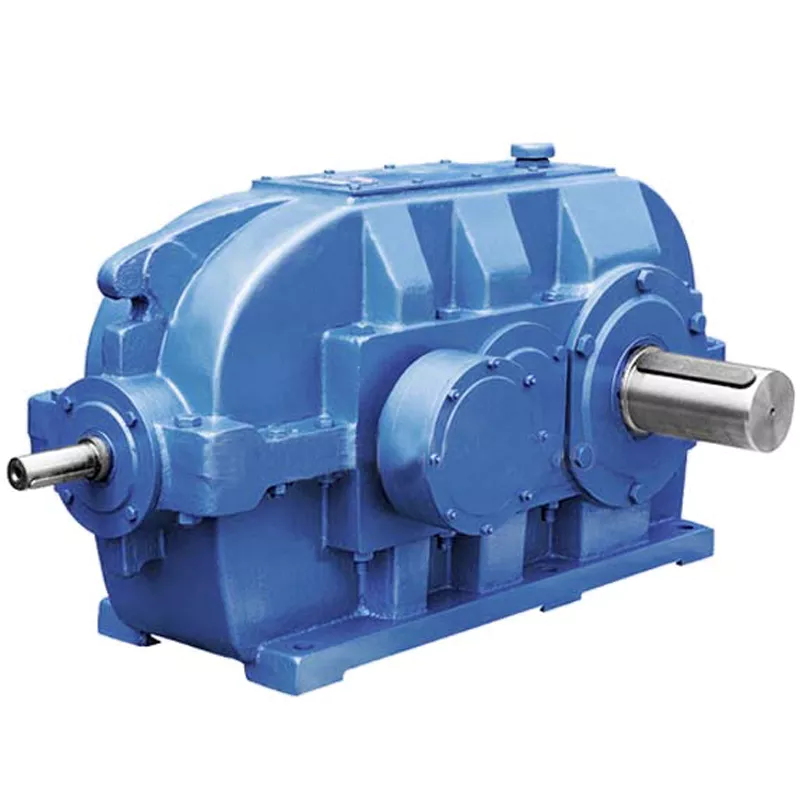
Advancements in Helical Gearbox Technology
Advancements in helical gearbox technology have led to improved performance, efficiency, and versatility. Here are some notable advancements:
- Material Innovations: The use of advanced materials, such as high-strength alloys and composites, has enhanced the durability and load-carrying capacity of helical gears. These materials also contribute to reduced weight and improved efficiency.
- Precision Manufacturing: Modern manufacturing techniques, including CNC machining and gear grinding, have enabled the production of helical gears with higher accuracy and tighter tolerances. This results in smoother operation and reduced noise levels.
- Gear Tooth Profile Optimization: Advanced computer simulations and modeling techniques allow for the optimization of gear tooth profiles. This results in better load distribution, reduced stress concentration, and improved overall gearbox efficiency.
- Lubrication and Cooling: Improved lubrication systems and cooling mechanisms help maintain optimal operating temperatures and extend the lifespan of helical gearboxes. This is particularly important for high-demand applications.
- Noise and Vibration Reduction: Innovative designs and precision manufacturing techniques have led to helical gears with reduced noise and vibration levels. This advancement is crucial for industries where noise reduction is a priority.
- Compact Design: Advancements in gear design and manufacturing have allowed for more compact and lightweight helical gearbox configurations, making them suitable for space-constrained environments.
- Integration with Electronics: Some modern helical gearboxes are designed for seamless integration with electronic control systems. This enables better monitoring, control, and optimization of gearbox performance.
- Customization: Advancements in manufacturing and design tools allow for greater customization of helical gearboxes to meet specific application requirements. This includes adapting gear ratios, sizes, and configurations.
In summary, advancements in helical gearbox technology have led to enhanced performance, durability, efficiency, and customization options. These innovations continue to make helical gearboxes a versatile and reliable choice for a wide range of industrial applications.
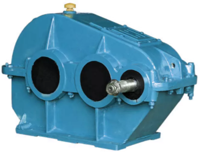
Handling Shock Loads and Sudden Changes in Torque in Helical Gearboxes
Helical gearboxes are designed to handle a range of operational conditions, including shock loads and sudden changes in torque. The helical design of the gears, which have slanted teeth that engage gradually, helps to distribute forces more evenly across the teeth compared to straight-cut gears. This design characteristic contributes to the gearbox’s ability to withstand sudden changes in torque and shock loads.
The gradual engagement of the helical teeth results in smoother and quieter operation, reducing the impact of abrupt torque changes. The slanted teeth also allow for more gradual transmission of force, which helps in dampening vibrations and minimizing stress concentrations that can occur in high-impact situations.
However, while helical gears are better suited for shock loads compared to straight-cut gears, it’s important to note that extreme shock loads or sudden torque changes can still impact the gearbox’s components over time. Manufacturers often take factors such as application requirements, load profiles, and anticipated shock loads into consideration when designing helical gearboxes to ensure reliable and durable performance.
Additionally, using appropriate lubrication and maintenance practices can further enhance the gearbox’s ability to handle shock loads and sudden torque changes. Regular inspection and timely maintenance help identify and address potential issues before they lead to component failure.

Limitations and Disadvantages of Helical Gear Systems
While helical gear systems offer numerous advantages, they also come with certain limitations and disadvantages:
- Axial Thrust: Helical gears generate axial thrust due to the helix angle of the teeth. This thrust can cause additional load on bearings and may require additional measures to counteract.
- Complex Manufacturing: The manufacturing process for helical gears is more complex than that of straight-toothed gears, which can lead to higher production costs.
- Axial Length: Helical gears require more axial space compared to spur gears with the same gear ratio. This can be a limitation in applications with space constraints.
- Sliding Contact: Helical gears have sliding contact between their teeth, which can result in higher friction and more heat generation compared to rolling contact gears.
- Efficiency: Although helical gears are generally efficient, their efficiency can be slightly lower than that of some other gear types, especially at high speeds.
- Complexity in Gearbox Design: The inclination of helical gear teeth introduces additional complexity in gearbox design and alignment.
- Reverse Thrust: In some cases, reverse thrust can occur when helical gears are subjected to high axial loads, leading to undesirable effects.
It’s important to consider these limitations and disadvantages when selecting gear systems for specific applications. Despite these challenges, helical gears remain a popular choice in various industries due to their benefits and overall performance characteristics.


editor by CX 2023-10-11
in Zaporizhzhya Ukraine sales price shop near me near me shop factory supplier Sintered DC Metal Planetary Gearbox Diameter 22mm with Motors Use for Automatic Teller Machine Driver, Automatic Rotary Advertising, Micro Geared Motor manufacturer best Cost Custom Cheap wholesaler

We can offer a entire-assortment of energy transmission merchandise like chains, sprockets and plate wheels, pulleys, gearboxes, motors, couplings, gears and racks. we provide a single-stop resolution for the acquire of mechanical energy transmission products in China. With several years’ knowledge in this line, we will be trustworthy by our rewards in aggressive cost, one-time delivery, prompt response, on-hand engineering support and good soon after-revenue companies.Additionally, all our production procedures are in compliance with ISO9001 specifications. We are a manufacturing facility EPTTized in metal elements EPT amp steel EPTT via powEPTTmetallurgy approach .
The P/M procedure is an cost-effective, environmentally clean, higher generation approach for creating areas precisely to or shut to final dimensions. With little or no machining functions essential.
At existing, components with a difficult form, limited-dimensional tolerances, managed density and homes can be created by powEPTTmetallurgy methods. A technological process of powEPTTmetallurgy ensures high fleXiHu (West EPT) Dis.bility in the selection of physiochemical homes and other demands, incXiHu (West EPT) Dis.Hu (West EPT) Dis.:
- Manufacturing of structural elements with sophisticated shapes .
- EPTTled porosity .
- EPT mechanical toughness and resistance to vibrations .
- EPTTled qualities.
- EPT mechanical toughness and resistance to vibrations.
- EPT production precision and good floor top quality
- Massive number of generation series .
- Good tolerances .
There are a few simple steps to powEPTTmetallurgy, the method employed to EPT powEPTTmetal EPTs. Initial, any of a quantity of techniques incXiHu (West EPT) Dis.Hu (West EPT) Dis. atomization, flaking, pulverization, chemical reduction and electrolytic are utilised to decrease the preliminary uncooked metallic materials to a fantastic dust or powder. Distinct quantities of this powEPTTare then placed into the compaction die or mold where strain is used from the two previously mentioned and beneath in exact quantities relevant to the particular components and intended use of the completed EPT. This mold is pre-fashioned and outcomes in the desired EPT form. After this type is ejected from the die, sintering is employed to fuse the powEPTTparticles collectively.Sintering is a warmth treatment method commonly employed to improve the energy and structural integrity of a presented material. PowEPTTmetallurgy processes use sintering to transform steel powders and other EPT materials into conclude-use elements. Sintering typically takes spot in a one, eEPTTated furnace with different temperature zones.
Custom metallic parts
A EPTT is a EPTT EPTT system to make large torque by reducing the EPT velocity or boost the EPT pace the other way. Planetary EPTT consisting three elements: EPTTEPT, world EPT and ring EPT . A EPTT EPT is a EPTwheel in a planetary EPT system, that rotates about its very own aXiHu (West EPT) Dis.s and has other EPTs (planet EPTs) that rotate close to it. A lot like the EPTT and planets in our photo voltaic technique. The amount of planetary EPTs in a EPTT may differ primarily based on the EPT ratio. Most planetary EPTTes have from two to five planet EPTs. When searching at planetary EPTs, the toughness of the EPTT is usually deterEPTd by the dimension of the EPTTEPT. Bigger EPTTEPTs will let for higher torque values. The planet provider,Its aim is to maintain up to EPTs of the exact same measurement, which mesh with the EPTTEPT.
Planetary EPTT positive aspects:
- Offers higher torque at slow speeds .
- The shafts are made up of hardened and tempered alloy steel .
- EPTT EPTs ,world EPTs and ring EPTs are created of powEPTTmetallurgy and sintering steel .
- Low noise levels.
- Great top quality EPTTr roller bearings for enter and output shafts .
- EPT performance .
Workshop

