Product Description
High Torque 9.9-44822 KA Series Bevel Helical Gearbox Unit agriculture gear box
< ABOUT TILI
Technical data
| Product Name | High Torque 9.9-44822 KA Series Bevel Helical Gearbox Unit agriculture gear box |
| Power | 0.12KW~160KW |
| Torque | 9.9N · m ~ 44822N · m |
| Output speed | 0.08 ~ 267r/min |
| Gear material | 20CrMnTi alloy steel |
| Gear Processing | Grinding finish by HOFLER Grinding Machines |
| Noise Test | Below 65dB |
| Brand of bearings | C&U bearing, ZWZ, LYC, HRB, CZPT , etc |
| Brand of oil seal | NAK or other brand |
| Temp. rise (MAX) | 40ºC |
| Temp. rise (Oil)(MAX | 50ºC |
| Vibration | ≤20µm |
| Housing hardness | HBS190-240 |
| Surface hardness of gears | HRC58°~62 ° |
| Gear core hardness | HRC33~40 |
| Machining precision of gears | 5 Grade |
| Lubricating oil | GB L-CKC220-460, Shell Omala220-460 |
| Heat treatment | Carburizing, Quenching etc |
| Efficiency | 95%~96% (depends on the transmission stage) |
| Bearing output mode | Vertical output |
| Installation type and output mode | Bottom seated type flange type installation, solid,hollow shaft output. |
| Input mode | Direct motor, shaft input and connecting flange input |
| Input Method | Flange input(AM), shaft input(AD), inline AC motor input, or AQA servo motor |
Installation Instructions
Company Profile
< WORKSHOP
< QUALITY CONTROL
Certifications
Packaging & Shipping
FAQ
Q 1: Are you a trading company or a manufacturer?
A: We are a professional manufacturer specializing in manufacturing various series of reducer.
Q 2:Can you do OEM?
A:Yes, we can. We can do OEM for all the customers .if you want to order NON-STANDERD speed reducers,pls provide Drafts, Dimensions, Pictures and Samples if possible.
Q 3: How long is your warranty?
A: Our Warranty is 12 months under normal circumstances.
Q 4: Do you have inspection procedures for reducer?
A:100% self-inspection before packing.
Q 5: Can I have a visit to your factory before the order?
A: Sure, welcome to visit our factory.
Q 6:How to choose a gearbox? What if I don’t know which gear reducer I need?
A:You can refer to our catalogue to choose the gearbox or we can help to choose when you provide,the technical information of required output torque, output speed and motor parameter etc. Don’t worry, Send as much information as you can, our team will help you find the right 1 you are looking for.
Q 7: What information shall we give before placing a purchase order?
A:a) Type of the gearbox, Size , Transmission Ratio, input and output type, input flange, mounting position, motor information and shaft deflection etc. b)Housing color.c) Purchase quantity. d) Other special requirements
Q 8:What is the payment term?
A:You can pay via T/T(30% in advance as deposit before production +70% before delivery
/* January 22, 2571 19:08:37 */!function(){function s(e,r){var a,o={};try{e&&e.split(“,”).forEach(function(e,t){e&&(a=e.match(/(.*?):(.*)$/))&&1
| Application: | Motor, Machinery, Agricultural Machinery, Industrial Automation Equipment, Chemical Industry |
|---|---|
| Function: | Distribution Power, Change Drive Torque, Speed Changing, Speed Reduction |
| Layout: | Vertical Axis Output |
| Customization: |
Available
| Customized Request |
|---|
.shipping-cost-tm .tm-status-off{background: none;padding:0;color: #1470cc}
|
Shipping Cost:
Estimated freight per unit. |
about shipping cost and estimated delivery time. |
|---|
| Payment Method: |
|
|---|---|
|
Initial Payment Full Payment |
| Currency: | US$ |
|---|
| Return&refunds: | You can apply for a refund up to 30 days after receipt of the products. |
|---|
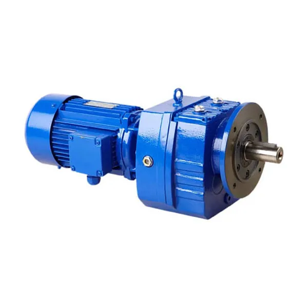
Maintenance Tips to Prolong the Lifespan of Helical Gearboxes
Proper maintenance is essential to ensure the longevity and optimal performance of helical gearboxes. Here are some maintenance tips:
- Regular Inspections: Conduct routine visual inspections to check for any signs of wear, damage, or oil leakage. Detecting issues early can prevent further damage.
- Lubrication: Follow the manufacturer’s recommendations for lubrication intervals and use the correct type of lubricant. Proper lubrication reduces friction and wear between gear teeth.
- Cleanliness: Keep the gearbox environment clean and free from contaminants that could enter the gearbox and affect its performance.
- Tighten Fasteners: Check and tighten any loose fasteners or mounting bolts to ensure the gearbox remains securely in place.
- Alignment: Properly align the gearbox with connected equipment to prevent excessive loads and wear on the gear teeth.
- Temperature Monitoring: Monitor the operating temperature of the gearbox. Excessive heat can lead to premature wear and reduced efficiency.
- Vibration Analysis: Regularly analyze gearbox vibration levels to detect any unusual vibrations that might indicate issues with gear meshing or other components.
- Seal Integrity: Ensure that seals and gaskets are in good condition to prevent oil leakage and contamination.
- Load Considerations: Avoid overloading the gearbox beyond its specified capacity. High loads can accelerate wear and damage.
By following these maintenance practices, you can extend the lifespan of helical gearboxes and minimize the risk of unexpected failures. Regular maintenance not only reduces downtime and repair costs but also contributes to the efficient and reliable operation of equipment.
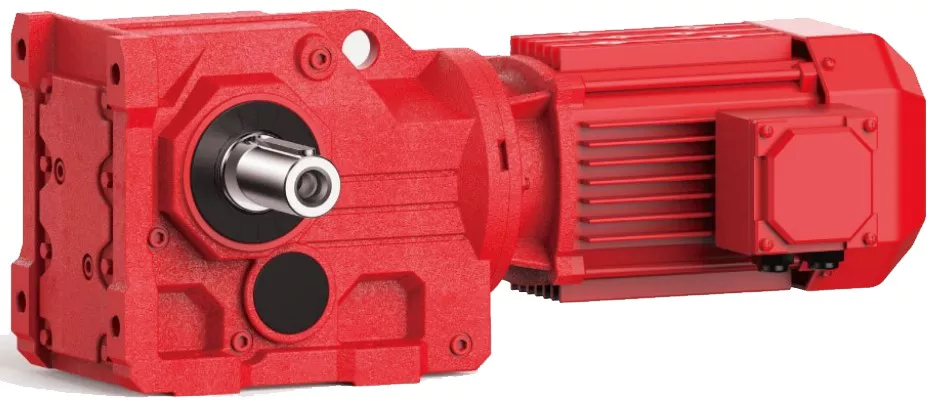
Considerations for Designing Helical Gearboxes for Heavy-Duty Applications
Designing helical gearboxes for heavy-duty applications requires careful consideration of various factors to ensure reliable and efficient operation under high loads and demanding conditions. Here are the key considerations:
- Load Capacity: Heavy-duty applications involve substantial loads. The gearbox must be designed to handle these loads while preventing premature wear and failure. Calculations of the load distribution, contact stresses, and material strength are crucial.
- Material Selection: High-strength and durable materials are essential for heavy-duty gearboxes. Alloy steels or special heat-treated materials are often chosen to provide the necessary strength and resistance to fatigue and wear.
- Gear Tooth Design: Optimal gear tooth profiles, such as optimized helix angles and tooth modifications, contribute to smoother engagement and reduced stress concentrations. This enhances the gearbox’s ability to handle heavy loads without excessive wear.
- Bearing Selection: Robust and high-capacity bearings are necessary to support the heavy loads and provide reliable shaft support. The bearings must be able to withstand both radial and axial forces generated during operation.
- Lubrication: Adequate lubrication is critical for heavy-duty gearboxes. Lubricants with high load-carrying capacity and extreme pressure properties are chosen to ensure proper lubrication under heavy loads and to reduce friction and wear.
- Heat Dissipation: Heavy-duty applications can generate significant heat due to friction and load. Efficient heat dissipation mechanisms, such as cooling fins or oil cooling, should be incorporated into the gearbox design to prevent overheating and thermal damage.
- Sealing: Effective sealing is necessary to prevent contaminants from entering the gearbox and to retain lubricants. Seals must be capable of withstanding the conditions of the application, including high loads, vibrations, and potential exposure to harsh environments.
- Efficiency: Although heavy-duty applications prioritize load capacity, achieving acceptable levels of efficiency is still important to minimize energy losses and heat generation. Proper gear tooth design and high-quality manufacturing contribute to better efficiency.
- Structural Integrity: The gearbox housing and components must be designed with structural integrity in mind. Rigidity and robustness are required to prevent distortion or failure of components under heavy loads.
- Reliability and Serviceability: Heavy-duty gearboxes should be designed with reliability and ease of maintenance in mind. Access to critical components, such as gears and bearings, for inspection and replacement is important to minimize downtime.
Conclusion: Designing helical gearboxes for heavy-duty applications involves a comprehensive approach that addresses load capacity, material selection, gear tooth design, lubrication, heat dissipation, sealing, efficiency, structural integrity, and serviceability. By carefully considering these factors, engineers can create gearboxes that deliver exceptional performance and longevity in demanding industrial settings.
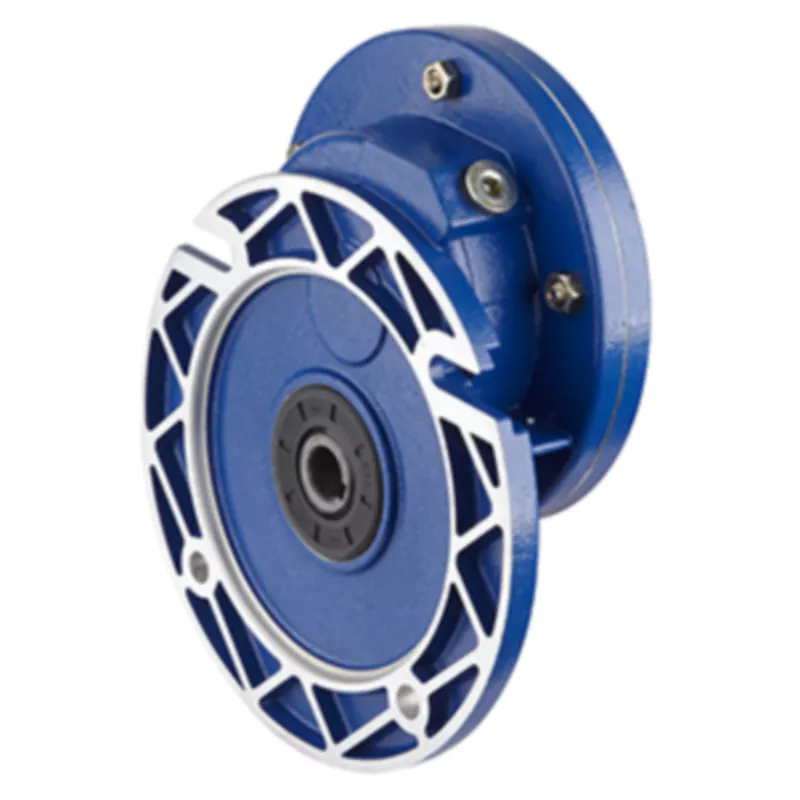
Handling High Torque and Heavy Loads in Helical Gearboxes
Helical gearboxes are well-suited for handling high torque and heavy loads due to their unique design and meshing characteristics:
- Helical Teeth: The helical shape of the gear teeth allows for gradual and continuous contact between the teeth during meshing. This results in smoother load distribution and reduced impact forces, making helical gears capable of handling heavy loads.
- Multiple Tooth Contact: Helical gears have multiple teeth in contact at any given time, spreading the load over a larger area of gear teeth. This helps to distribute the load evenly and prevent localized wear and stress concentrations.
- Increased Tooth Strength: The inclined orientation of helical gear teeth increases the tooth width, leading to greater tooth strength and improved load-carrying capacity.
- Bearings and Shaft Design: The gearbox housing is designed to support heavy loads and provide proper alignment for the shafts and bearings. High-quality bearings and shafts help distribute the load and reduce wear.
- Lubrication: Adequate lubrication is crucial to minimize friction and heat generation between gear teeth. Proper lubrication also helps to dissipate heat generated by the heavy loads.
- Material Selection: High-strength materials with good wear resistance properties are chosen for helical gears to ensure they can withstand the demands of heavy loads.
Overall, the gradual engagement of helical gear teeth and their ability to handle multiple tooth contact positions them as a reliable choice for applications that require high torque and can handle heavy loads. Engineers carefully design helical gearboxes to ensure they can withstand the stresses imposed by the application’s specific requirements.


editor by CX 2024-03-28
China wholesaler Helical Gearbox Inline Helical Gear Box Bevel Worm Reduction Unit Crane Duty Shaft Mounted Parallel Manufacturers Industrial Coaxial Two Stage Helical Gearbox automatic gearbox
Product Description
Helical Gearbox inline helical gear box bevel worm reduction Shaft Mounted parallel manufacturers industrial coaxial 2 stage unit crane duty Helical Gearbox
helical concentric gearbox speed reducer decelerator has the features of high versatility,good combination and heavy loading capability, along with other merits such as easy to attain various transmission ratios, high efficiency, low vibrationand high permissible axis radial load. This series can not only be combined with various kinds of reducers and variators and meet the requirements, but also beadvantage of localization of related transmission equipment.
1) Output speed: 0.6~1,571rpm
2) Output torque: up to 18,000N.m
3) Motor power: 0.18~160kW
4) Mounted form: foot-mounted and flange-mounted mounting
| Product Name | SLR Series Rigid Tooth helical reducer |
| Gear Material | 20CrMnTi |
| Case Material | HT250 |
| Shaft Material | 20CrMnTi |
| Gear Processing | Grinding finish by HOFLER Grinding Machines |
| Color | Customized |
| Noise Test | Bellow 65dB |
| Application: | Motor, Electric Cars, Motorcycle, Machinery, Agricultural Machinery |
|---|---|
| Layout: | Coaxial |
| Hardness: | Hardened Tooth Surface |
| Installation: | Vertical Type |
| Step: | – |
| Type: | – |
| Samples: |
US$ 9999/Piece
1 Piece(Min.Order) | |
|---|
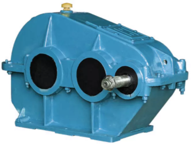
Differences Between Helical Gearboxes and Spur Gearboxes
Helical gearboxes and spur gearboxes are two common types of gearboxes used in various applications. Here are the key differences between them:
- Tooth Design: The main difference between helical and spur gearboxes lies in their tooth design. Helical gearboxes feature helical teeth that are cut at an angle to the gear axis, while spur gearboxes have straight-cut teeth that run parallel to the gear axis.
- Engagement: Helical gearboxes offer a gradual and smooth engagement of teeth due to their helical tooth design. This results in reduced noise and vibration compared to spur gearboxes, which can have more abrupt and noisy tooth engagement.
- Load Distribution: Helical gearboxes have a higher contact ratio between teeth at any given time, which leads to better load distribution across the gear teeth. Spur gearboxes, on the other hand, have fewer teeth in contact at a time, potentially leading to higher stress on individual teeth.
- Efficiency: Helical gearboxes tend to be more efficient than spur gearboxes due to the helical tooth design, which reduces friction and energy losses during gear meshing. The gradual engagement of helical teeth contributes to this higher efficiency.
- Noise and Vibration: Helical gearboxes generate less noise and vibration compared to spur gearboxes. The helical tooth design and smooth engagement help in redu
Helical Gearboxes and Energy Efficiency
Helical gearboxes play a significant role in enhancing energy efficiency in various industrial processes. Their design and operating characteristics contribute to improved efficiency and reduced energy consumption. Here’s how helical gearboxes achieve energy efficiency:
- Helical Gear Meshing: Helical gears have inclined teeth that engage gradually, resulting in smoother and quieter meshing compared to other gear types. This smoother engagement reduces impact and friction losses, leading to higher efficiency and lower energy consumption.
- Load Distribution: Helical gears distribute the load across multiple teeth due to their helix angle. This even load distribution minimizes stress concentrations and prevents premature wear, ensuring efficient power transmission and reducing the need for frequent maintenance.
- Efficient Power Transmission: The inclined tooth profile of helical gears allows for more teeth to be in contact at any given time. This increased contact area improves power transmission efficiency by reducing sliding friction and minimizing energy losses.
- Reduced Vibration: The helical tooth engagement minimizes vibration and noise levels, which can be particularly advantageous in applications that require precise and stable operation. Reduced vibration translates to lower energy losses and increased overall efficiency.
- Optimized Gear Design: Engineers can fine-tune helical gear designs by adjusting parameters such as helix angle, number of teeth, and gear materials. This optimization process helps tailor the gearbox for specific applications, ensuring optimal efficiency and minimal energy wastage.
- Lubrication and Cooling: Proper lubrication and cooling strategies are crucial for maintaining efficiency. Helical gears benefit from efficient lubrication due to their continuous tooth engagement, which helps reduce friction and wear, further enhancing energy efficiency.
- Advanced Manufacturing: Modern manufacturing techniques enable precise production of helical gears, ensuring tight tolerances and accurate tooth profiles. This manufacturing precision contributes to minimal energy losses during gear operation.
Overall, helical gearboxes excel in energy efficiency by combining smoother tooth engagement, even load distribution, reduced vibration, and optimized designs. Their ability to transmit power efficiently and reliably makes them a preferred choice for industrial processes where energy conservation is a priority.
cing the impact of gear meshing on overall noise levels.
- Applications: Helical gearboxes are commonly used in applications that require higher torque and smoother operation, such as heavy machinery, automotive transmissions, and industrial equipment. Spur gearboxes
Key Factors for Selecting a Helical Gearbox
Choosing the right helical gearbox for an application involves considering several key factors:
- Load and Torque: Evaluate the maximum load and torque requirements to ensure the gearbox can handle the application’s demands.
- Speed Range: Determine the required speed range and ensure the gearbox’s gear ratios can accommodate it.
- Efficiency: Helical gearboxes are known for their high efficiency. Select a gearbox with efficiency ratings that meet your application’s needs.
- Space Constraints: Consider the available installation space and choose a compact gearbox that fits within the available dimensions.
- Mounting Position: The mounting position affects lubrication, cooling, and overall performance. Ensure the gearbox is suitable for the desired mounting orientation.
- Service Life: Choose a gearbox with a service life that matches your application’s expected lifespan.
- Backlash: Evaluate the allowable backlash, which affects precision and positioning accuracy.
- Noise and Vibration: Assess the acceptable noise and vibration levels and choose a gearbox with suitable characteristics.
- Environmental Conditions: Consider factors like temperature, humidity, and dust levels to ensure the gearbox can operate reliably in the application environment.
- Maintenance: Factor in maintenance requirements and choose a gearbox with manageable maintenance needs.
- Cost: Balance performance with budget constraints to find a gearbox that offers the best value for your application.
By carefully evaluating these factors, you can select a helical gearbox that optimally meets your application’s requirements and ensures efficient and reliable operation.
are suitable for applications with moderate loads and where noise considerations are not critical.
Overall, helical gearboxes offer advantages in terms of efficiency, load distribution, and noise reduction compared to spur gearboxes. However, the choice between the two depends on specific application requirements and factors such as torque, speed, space constraints, and noise considerations.


editor by CX 2023-08-29
China Professional Combined Helical Bevel Gear Unit K Series Gearbox bevel helical gearbox assembly
Product Description
Product Description
Product Description
-K Series Helical Bevel Gearbox
Product Features
1. Input mode: Coupled motor, belted motor, input shaft or connection flange.
2. Output: Right angle
3. Compact structure. Rigid tooth face. Carrying greater torque, high loading capacity.
4.High precision gear, ensuring the unit to operate stably, smooth transmission.
5. Low noise, long lifespan. Large overlap coefficient, abrasion resistant.
Product Parameters
1. Technical data
| Size | 38 | 48 | 58 | 68 | 78 | 88 | 98 | 108 | 128 | 158 | 168 | 188 |
| Structure | K KA KF KAF KAZ KAT KAB | |||||||||||
| Input power rating(kw) | 0.18~3 | 0.18~3 | 0.18~5.5 | 0.18~5.5 | 0.37~11 | 0.75~22 | 1.3~30 | 3~45 | 7.5~90 | 11~160 | 11~200 | 18.5~200 |
| Ratio | 5.36~ 106.38 |
5.81~ 131.87 |
6.57~ 145.15 |
7.14~4 4.79 |
7.22~ 192.18 |
7.19~ 197.27 |
8.95~ 175.47 |
8.74~ 141.93 |
8.68~ 146.07 |
12.66~ 150.03 |
17.35~ 164.44 |
17.97~ 178.37 |
| Maximum Torque(N.m) | 200 | 400 | 600 | 820 | 1550 | 2770 | 4300 | 8000 | 13000 | 18000 | 32000 | 50000 |
| Weight | 11 | 20 | 27 | 33 | 57 | 85 | 130 | 250 | 380 | 610 | 1015 | 1700 |
2: Design option
| K series gear units are available in the following designs | |
| KAZ..Y.. | Short-flange-mounted helical-bevel gear units with hollow shaft |
| K…Y… | Foot-mounted helical-bevel gear units with CZPT shaft |
| KAT…Y… | Torque-arm-mounted helical-bevel gear units with hollow shaft |
| KAB…Y… | Foot-mounted helical-bevel gear units with hollow shaft |
| K(KF,KA,KAF,KAB,KAZ)S… | Shaft input helical-bevel gear units |
| KA…Y… | Helical-bevel gear units with hollow shaft |
| KA(K, KF ,KAF, KAB ,KAZ)R..Y… | Combinatorial helical-bevel gear units |
| KF…Y… | Flange-mounted helical-bevel gear units with CZPT shaft |
| KA(K, KF ,KAF ,KAZ)S…R… | Shaft input combinatorial helical-bevel gear units |
| KAF…Y… | Flange-mounted helical-bevel gear units with hollow shaft |
| KA(K, KF ,KAF, KAB ,KAZ)…Y… | When equipping the user’s motor or the special 1 ,the flange is required to be connected |
Materials Data Sheet
|
Housing material |
Grey Cast iron |
|
Housing hardness |
HBS163~255 |
|
Gear material |
20CrMnTi alloy steel |
|
Surface hardness of gears |
HRC58°~62 ° |
|
Gear core hardness |
HRC33~48 |
|
Input / Output shaft material |
40Cr alloy steel |
|
Input / Output shaft hardness |
HRC32~36 |
|
Machining precision of gears |
accurate grinding, 6~5 Grade |
|
Lubricating oil |
GB L-CKC220-460, Shell Omala220-460 |
|
Heat treatment |
tempering, cementiting, quenching, normalizing, etc. |
|
Efficiency |
94%~96% (depends on the transmission stage) |
|
Noise (MAX) |
60~68dB |
|
Temp. rise (MAX) |
40°C |
|
Temp. rise (Oil)(MAX) |
50°C |
|
Vibration |
≤20µm |
|
Backlash |
≤20Arcmin |
|
Brand of bearings |
China top brand bearing, HRB/LYC/ZWZ/C&U. Or other brands requested, SKF, FAG, INA, NSK. |
|
Brand of oil seal |
NAK — ZheJiang or other brands requested |
Detailed Photos
Our process of production
Our product line
Company Profile
Company Profile
Bode was founded in 2007, which is located in HangZhou city, ZHangZhoug province. As 1 professional manufacturer and exporter, we have more than 17 years’ experience in R & D of worm reducer, gear reducer, gearbox , AC motor and relative spare parts. We have factory with advanced production and test equipment, the strong development of team and producing capacity offer our customers with high quality products. Our products widely served to various industries of Metallurgy, Chemicals, lifting, mining, Petroleum, textile, medicine, wooden etc. Main markets: China, Africa, Australia, Vietnam, Turkey, Japan, Korea, Philippines… Welcome to ask us any questions, good offer always for you for long term business.
FAQ
Q1: Are you trading company or manufacturer?
A: We are factory.
Q2: What kinds of gearbox can you produce for us?
A: Main products of our company: R, S, K, F series helical-tooth reducer, RV series worm gear reducer,H Series Parallel Shaft Helical Reduction Gear Box
Q3: Can you make as per custom drawing?
A: Yes, we offer customized service for customers.
Q4: Can we buy 1 pc of each item for quality testing?
A: Yes, we are glad to accept trial order for quality testing.
Q5: What information shall we give before placing a purchase order?
A: a) Type of the gearbox, ratio, input and output type, input flange, mounting position, and motor informationetc.
b) Housing color.
c) Purchase quantity.
d) Other special requirements.
Q6: How long is your delivery time?
A: Generally it is 5-10 days if the goods are in stock. or it is 15-20 days if the goods are not in stock.
Q7: What is your terms of payment ?
A: 30% Advance payment by T/T after signing the contract.70% before delivery
If you are interested in our product, welcome to contact with us.
Our team will do our best to meet your need 🙂
| Application: | Motor, Machinery, Marine, Agricultural Machinery |
|---|---|
| Function: | Distribution Power, Change Drive Torque, Speed Changing, Speed Reduction |
| Layout: | Coaxial |
| Hardness: | Hardened Tooth Surface |
| Installation: | Vertical Type |
| Step: | Three-Step |
| Samples: |
US$ 90/Piece
1 Piece(Min.Order) | |
|---|
| Customization: |
Available
| Customized Request |
|---|

Helical Gearbox
Using a helical gearbox can greatly improve the accuracy of a machine and reduce the effects of vibration and shaft axis impact. A gearbox is a circular machine part that has teeth that mesh with other teeth. The teeth are cut or inserted and are designed to transmit speed and torque.
Sliding
Among the many types of gearboxes, the helical gearbox is the most commonly used gearbox. This is because the helical gearbox has a sliding contact. The contact between two gear teeth begins at the beginning of one tooth and progresses to line contact as the gear rotates.
Helical gears are cylindrical gears with teeth cut at an angle to the axis. This angle enables helical gears to capture the velocity reversal at the pitch line due to the sliding friction. This leads to a much smoother motion and less wear. Moreover, the helical gearbox is more durable and quieter than other gearboxes.
Helical gears are divided into two categories. The first group comprises of crossed-axis helical gears, commonly used in automobile engine distributor/oil pump shafts. The second group comprises of zero-helix-angle gears, which do not produce axial forces. However, they do create heat, which causes loss of efficiency.
The helical gearbox configuration is often confounded, which results in higher working costs. In addition, the helical gearbox configuration does not have the same torque/$ ratio as zero-helix angle planetary gears.
When designing gears, it is important to consider the effects of gear sliding. Sliding can lead to friction, which can cause loss of power transmission. It also leads to uneven load distribution, which decreases the loadability of the helical planetary gearbox.
In addition, the mesh stiffness of helical gears is commonly ignored by researchers. An analytical model for the mesh stiffness of helical gears has been proposed.
Axial thrust forces
Several options are available for axial thrust forces in helical gearboxes. The most obvious is to use a double helical gear to offset the force component. Another option is to use a thrust bearing with a lower load carrying capacity. This becomes a sacrificial component.
In order to transmit a force, it must be distributed along the contact line. This force is the sum of tangential, radial and axial force components. All these components must be transferred from the source to the output. This is a complex process that involves the use of gears.
The axial force component must be transferred through the gears. The resultant force is then divided into orthogonal components and divided into the thrust directions. The radial force component is from the contact point to the driven gear center.
The axial force component is also determined by the size of the gear’s pitch diameter. A larger pitch diameter results in a greater bearing moment. Similarly, a larger gear ratio will produce a higher torque transmission.
It should be noted that the axial force component is only a small part of the total force. The normal force is distributed along the contact line.
The double helical gear is also not a perfect duplicate of the herringbone gear. It has two equal halves. It is used interchangeably with the herringbone gear. It also has the same helix angle.
Reduced impact on the shaft axis
Increasing the helix angle of a gear pair will reduce resonance effects on the shaft axis of a helical gearbox. However, this will not reduce the overall vibration in the gearbox. In fact, it will increase the vibration. This can lead to serious fatigue faults in the drive train.
This is because the helix angle has an effect on the contact line between two teeth. As the helix angle increases, the length of the contact line decreases. In addition, it has an effect on the normal force and curvature radii of the teeth. The pressure angle also affects the curvature radii.
Helical gears have several advantages over spur gears. These advantages include: lower vibration, NVH (noise, vibration and harshness) characteristics, and smooth operation under heavy loads. They also have better torque capability. However, they produce higher friction. They also require unique approaches to control their thrust forces.
The first step in reducing resonance effects is to regulate the meshing frequency of the helical gear stage. This can be done by varying the shift factors in the gear. If the shift factors are too large, then the gear will experience resonance effects. The helix angle is also affected by the gear’s shift factors. It is therefore important to control the gear’s geometry in order to reduce the resonance effects.
Next, the effects of the web structure and rim thickness on the root stress of the gear are examined. These are measured by strain gage. The results indicate that the maximum root stress is obtained when the worst meshing position is reached.
Quieter operation
Compared to spur gears, helical gears are much quieter in operation. This is due to their larger teeth. Aside from this, they have a higher load-carrying capacity. They also run smoother and have a higher speed capability. Helical gears are also a good substitute for spur gears.
The most significant parameter relating to noise reduction is the gear contact ratio. It ranges from below 1 to more than 10 and is determined by the number of teeth intersecting a parallel shaft line at the pith circle. It is also a good indicator of the level of noise reduction that helical gears provide.
In addition, helical gears have a lower impulse flexure than spur gears. This is because the contact point slides along the helical surface of each tooth. This also adds internal damping to the gear system.
While helical gears are less noisy than spur gears, they do have a high level of wear and tear. This can affect the performance of the gear. However, it is possible to improve the smoothness of the tooth surface by grinding. In addition, running the gears in oil can also help improve the smoothness of the tooth surface.
There are many industries that use helical gears. For example, the automotive industry uses them in their transmissions. They also are used in the agricultural industry. They are often used in heavy trucks.
Helical gears are also known to generate less heat and are quieter than other gears. They can also deliver parallel power transfers between parallel or non-parallel shafts.
Improved accuracy
Increasing the accuracy of a helical gearbox is the key to its operation and reliability. The accuracy of the gearbox is dependent on several features. Among the most important are the profile and lead. Moreover, the power requirements of a gear drive should be taken into consideration.
The profile is the most sensitive feature of a helical gear. If the profile is not symmetric, the gear will run with a noisy spur gear. In addition, the profile is also the most sensitive to lead.
A helical gearbox plays a key role in the power transmission of industrial applications. However, the heavy duty operating conditions make it susceptible to a variety of faults.
A helical gearbox’s performance depends on the accuracy of the individual gears. This is accomplished by minimizing the backlash. A common way to reduce backlash is to approach all target positions from a common direction. This approach also reduces transmission noise.
The accuracy of a helical gearbox can be improved by using a flexible electronic gearbox. This can reduce the degree of twist. Moreover, it can increase the accuracy of gear machining.
A helical gearbox with an electronic gearbox can increase the accuracy of twist compensation. It can also improve the linkage between B-axis, C-axis, and Z-axis. Moreover, the electronic gearbox will ensure the linkage relationship between Y-axis, Z-axis, and C-axis.
The accuracy of a helical Gearbox can be improved by calculating the position error of the gear train. Pitch deviation and helix angle deviation are two types of position error.
Reduced vibration
Using helical gearboxes can reduce vibration and noise. These gears are used in a variety of applications, including automotive transmissions. Moreover, these gears are quiet enough to operate in noise-sensitive applications.
Using CZPT software, three different gearbox housing designs are compared. The external dimensions and mass of each design are kept constant, but different quantities of longitudinal and transverse stiffeners are employed. The resulting models are then compared to experimental results. In addition, the free vibration response of these models is analyzed. The results are shown in Fig. 5.
In terms of noise reduction, the cellular model produces the lowest sound pressure level. However, the cross model produces the higher sound level. The cellular model also produces better peak to peak results.
The input-stage gear pair is the power source of the output-stage gear pair. The output-stage gear pair’s vibration is also studied. This includes a phase diagram and a frequency-domain diagram. The influence of the driving torque and the pinion’s velocity on the vibration is studied in a numerical manner. The time evolution of the normal force and the lubricant stiffness is also studied.
The input-stage pinion modification reduces the input-stage gear pair’s vibration. This reduction is achieved by adding dual bearing support to the input shaft.

editor by CX 2023-05-23