Product Description
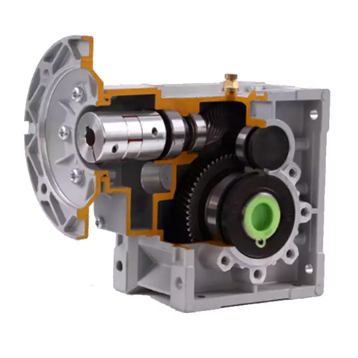
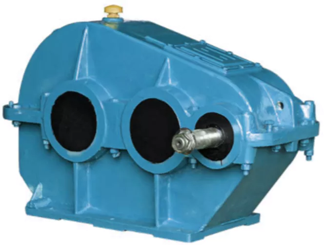
F series gear reducer is 1 kind of parallel shaft helical gear reducer , which consist of 2 or 3 stageshelical
gears (relate to gear ratio) in the same case . The hard tooth surface gear use the high quality alloy steel ,the
process of carburizing and quenching, grinding ,which give it follow characters :Stable transmission ,low noise
and temperature ,high loading ,long working lift . Wide application ,specialize in Metallurgy ,Sewage treatment,
Chemical Industry , Pharmacy ,Agriculture equipment and Oil industry
Specifications:
1) Output speed: 0.6~1,571r/min
2) Output torque: up to 21700N.m
3) Motor power: 0.12~200kW
4) Mounted form: foot-mounted and flange-mounted mounting
Product Description
Product Advantages
|
F Series Gearbox Reducer |
|
|
Product name |
F series of the gearbox hollow shaft model F107 oil seal transmission gearbox reducer reduction |
|
Warranty |
1 years |
|
Applicable Industries |
Manufacturing Plant |
|
Weight (KG) |
50KG |
|
Customized support |
OEM |
|
Gearing Arrangement |
Helical |
|
Output Torque |
1.8-2430N.M |
|
Input Speed |
1440, 2800,960,750 |
|
Output Speed |
0.5 to 200 |
|
Place of Origin |
China |
|
Product name |
F Series Parallel Shaft Gearbox Reducer |
|
Application |
Hardened Tooth Surface |
|
Installation |
Horizontal Type |
|
Layout |
Coaxial |
|
Gear Shape |
Helical |
|
Production Capacity |
800-1500PCS /Month |
|
Type |
Gear Reduction Motor |
|
Color |
Blue,Sliver or Customized |
|
Packing |
Wooden Box |
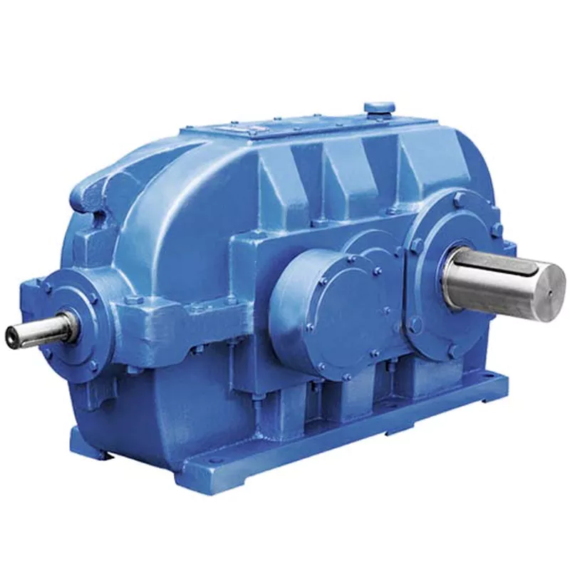
F series Parallel Shaft Helical Gear Reducer
Helical gear hard tooth surface structure, 2 / 3 gear combinations can be selected to achieve the required speed ratio, with reinforced cast iron shell, high bearing capacity, can be matched with different types of motors, small size, light weight, large
torque, stable operation and low noise.
Our Advantages
Certifications
| Hardness: | Hardened Tooth Surface |
|---|---|
| Installation: | Horizontal Type |
| Layout: | Parallel |
| Gear Shape: | Bevel Gear |
| Step: | Single-Step |
| Type: | Gear Reducer |
| Samples: |
US$ 500/Piece
1 Piece(Min.Order) | |
|---|

Installation and Alignment of Helical Gearboxes
Proper installation and alignment of a helical gearbox are essential to ensure its optimal performance and longevity. Here are the steps involved:
- Preparation: Gather all necessary tools, equipment, and safety gear. Ensure the work area is clean and well-lit.
- Mounting: Position the gearbox on the designated mounting surface and secure it using appropriate bolts. Follow the manufacturer’s guidelines for mounting torque and procedures.
- Shaft Alignment: Use precision tools such as dial indicators to align the input and output shafts. Achieving accurate shaft alignment minimizes stress on the gears and bearings.
- Bolt Tightening: Gradually and evenly tighten the mounting bolts, ensuring the gearbox remains properly aligned. Refer to torque specifications provided by the manufacturer.
- Lubrication: Fill the gearbox with the recommended lubricant according to the manufacturer’s specifications. Proper lubrication is crucial for reducing friction and wear.
- Alignment Check: After tightening the bolts, recheck the shaft alignment to ensure it hasn’t shifted during the tightening process.
- Run-In Period: Gradually introduce load to the gearbox to allow the gears to seat properly. Monitor the gearbox for any unusual noises, vibrations, or temperature changes during this period.
- Final Checks: Verify that the gearbox operates smoothly, without excessive noise or vibrations. Monitor the gearbox’s temperature during operation to ensure it remains within recommended limits.
- Regular Inspection: Schedule periodic inspections to check for any signs of wear, misalignment, or leakage. Address any issues promptly to prevent further damage.
It’s important to follow the manufacturer’s installation and alignment guidelines specific to the helical gearbox model you’re working with. Improper installation and alignment can lead to premature wear, reduced efficiency, and potential failure of the gearbox.

Handling Shock Loads and Sudden Changes in Torque in Helical Gearboxes
Helical gearboxes are designed to handle a range of operational conditions, including shock loads and sudden changes in torque. The helical design of the gears, which have slanted teeth that engage gradually, helps to distribute forces more evenly across the teeth compared to straight-cut gears. This design characteristic contributes to the gearbox’s ability to withstand sudden changes in torque and shock loads.
The gradual engagement of the helical teeth results in smoother and quieter operation, reducing the impact of abrupt torque changes. The slanted teeth also allow for more gradual transmission of force, which helps in dampening vibrations and minimizing stress concentrations that can occur in high-impact situations.
However, while helical gears are better suited for shock loads compared to straight-cut gears, it’s important to note that extreme shock loads or sudden torque changes can still impact the gearbox’s components over time. Manufacturers often take factors such as application requirements, load profiles, and anticipated shock loads into consideration when designing helical gearboxes to ensure reliable and durable performance.
Additionally, using appropriate lubrication and maintenance practices can further enhance the gearbox’s ability to handle shock loads and sudden torque changes. Regular inspection and timely maintenance help identify and address potential issues before they lead to component failure.

Limitations and Disadvantages of Helical Gear Systems
While helical gear systems offer numerous advantages, they also come with certain limitations and disadvantages:
- Axial Thrust: Helical gears generate axial thrust due to the helix angle of the teeth. This thrust can cause additional load on bearings and may require additional measures to counteract.
- Complex Manufacturing: The manufacturing process for helical gears is more complex than that of straight-toothed gears, which can lead to higher production costs.
- Axial Length: Helical gears require more axial space compared to spur gears with the same gear ratio. This can be a limitation in applications with space constraints.
- Sliding Contact: Helical gears have sliding contact between their teeth, which can result in higher friction and more heat generation compared to rolling contact gears.
- Efficiency: Although helical gears are generally efficient, their efficiency can be slightly lower than that of some other gear types, especially at high speeds.
- Complexity in Gearbox Design: The inclination of helical gear teeth introduces additional complexity in gearbox design and alignment.
- Reverse Thrust: In some cases, reverse thrust can occur when helical gears are subjected to high axial loads, leading to undesirable effects.
It’s important to consider these limitations and disadvantages when selecting gear systems for specific applications. Despite these challenges, helical gears remain a popular choice in various industries due to their benefits and overall performance characteristics.


editor by CX 2023-10-08