Product Description
Why Choose Us
Product Details
|
Type |
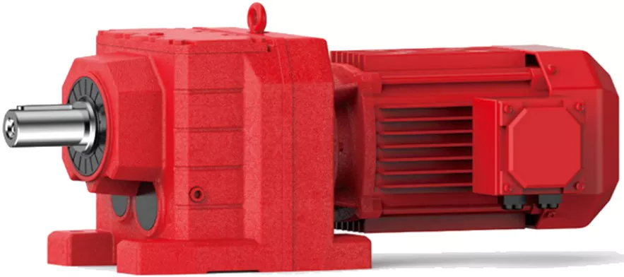
Inline Helical Gearbox / Reducer |
|
Model |
WR17~WR167 |
|
Mounting Position |
Flange, hollow shaft, CZPT shaft |
|
Efficiency |
94%~98%(depends on the transmission stage) |
|
Material |
Housing: HT250 high strength cast iron |
|
Gear: 20CrMnTi |
|
|
Surface hardness of gears |
HRC58~62 |
|
Input/output shaft material |
40Cr |
|
Machining precision of gears |
Accurate grinding, 6 grade |
|
Warranty |
1 Year |
|
Input Power |
0.09kw,0.18kw,1.1KW,1.5KW,2.2KW,3KW,4KW,5.5KW,7.5KW, 11Kw and so on. |
|
Usages |
Industrial Machine: Food Stuff, Ceramics, CHEMICAL, Packing, Dyeing, Wood working, Glass. |
|
IEC Flange |
IEC standard flange |
|
Lubricant oil |
Gear oil |
Company Profile
Exhibition
Customized Service
Certificate&Honor
Customer Comments
FAQ
1. How to choose a gearbox which meets our requirement?
You can refer to our catalogue to choose the gearbox or we can help to choose when you provide
the technical information of required output torque, output speed and motor parameter etc.
2. What information shall we give before placing a purchase order?
a) Type of the gearbox, ratio, input and output type, input flange, mounting position, and motor information etc.
b) Housing color.
c) Purchase quantity.
d) Other special requirements.
3. What industries are your gearboxes being used?
Our gearboxes are widely used in the areas of textile, food processing, beverage, chemical industry,
escalator,automatic storage equipment, metallurgy, tabacco, environmental protection, logistics and etc.
4. Do you sell motors?
We have stable motor suppliers who have been cooperating with us for a long-time. They can provide motors
with high quality.
/* January 22, 2571 19:08:37 */!function(){function s(e,r){var a,o={};try{e&&e.split(“,”).forEach(function(e,t){e&&(a=e.match(/(.*?):(.*)$/))&&1
| Application: | Motor, Machinery, Agricultural Machinery |
|---|---|
| Function: | Distribution Power, Change Drive Torque, Speed Changing, Speed Reduction, Speed Increase |
| Layout: | Coaxial |
| Samples: |
US$ 120/Piece
1 Piece(Min.Order) | Order Sample |
|---|
| Customization: |
Available
| Customized Request |
|---|
.shipping-cost-tm .tm-status-off{background: none;padding:0;color: #1470cc}
|
Shipping Cost:
Estimated freight per unit. |
about shipping cost and estimated delivery time. |
|---|
| Payment Method: |
|
|---|---|
|
Initial Payment Full Payment |
| Currency: | US$ |
|---|
| Return&refunds: | You can apply for a refund up to 30 days after receipt of the products. |
|---|

Types of Helical Gear Arrangements
Yes, there are different types of helical gear arrangements available to suit various applications and requirements. Some of the common helical gear arrangements include:
Parallel Shaft Arrangement: In this arrangement, the axes of the driving and driven shafts are parallel to each other. It is the most straightforward configuration and is often used in applications where space is not a constraint, and the gearboxes can be placed side by side.
Right-Angle Shaft Arrangement: In a right-angle arrangement, the driving and driven shafts are positioned at a 90-degree angle to each other. This arrangement is space-saving and is commonly used in applications where the layout requires a change in direction of the power transmission.
Double Helical Gear Arrangement (Herringbone Gears): Double helical gears consist of two sets of helical teeth facing each other. This arrangement helps to cancel out axial forces and reduces the net thrust load on bearings. It is often used in heavy-duty applications to minimize wear and vibration.
Crossed Helical Gear Arrangement (Screw Gears): In this configuration, the axes of the driving and driven shafts are neither parallel nor intersecting. It is suitable for applications requiring non-parallel and non-intersecting shafts.
The choice of helical gear arrangement depends on factors such as available space, power transmission requirements, and the desired layout of the machinery or equipment. Each arrangement has its advantages and disadvantages, and selecting the appropriate one is crucial for achieving optimal performance and efficiency.

Handling Shock Loads and Sudden Changes in Torque in Helical Gearboxes
Helical gearboxes are designed to handle a range of operational conditions, including shock loads and sudden changes in torque. The helical design of the gears, which have slanted teeth that engage gradually, helps to distribute forces more evenly across the teeth compared to straight-cut gears. This design characteristic contributes to the gearbox’s ability to withstand sudden changes in torque and shock loads.
The gradual engagement of the helical teeth results in smoother and quieter operation, reducing the impact of abrupt torque changes. The slanted teeth also allow for more gradual transmission of force, which helps in dampening vibrations and minimizing stress concentrations that can occur in high-impact situations.
However, while helical gears are better suited for shock loads compared to straight-cut gears, it’s important to note that extreme shock loads or sudden torque changes can still impact the gearbox’s components over time. Manufacturers often take factors such as application requirements, load profiles, and anticipated shock loads into consideration when designing helical gearboxes to ensure reliable and durable performance.
Additionally, using appropriate lubrication and maintenance practices can further enhance the gearbox’s ability to handle shock loads and sudden torque changes. Regular inspection and timely maintenance help identify and address potential issues before they lead to component failure.

Limitations and Disadvantages of Helical Gear Systems
While helical gear systems offer numerous advantages, they also come with certain limitations and disadvantages:
- Axial Thrust: Helical gears generate axial thrust due to the helix angle of the teeth. This thrust can cause additional load on bearings and may require additional measures to counteract.
- Complex Manufacturing: The manufacturing process for helical gears is more complex than that of straight-toothed gears, which can lead to higher production costs.
- Axial Length: Helical gears require more axial space compared to spur gears with the same gear ratio. This can be a limitation in applications with space constraints.
- Sliding Contact: Helical gears have sliding contact between their teeth, which can result in higher friction and more heat generation compared to rolling contact gears.
- Efficiency: Although helical gears are generally efficient, their efficiency can be slightly lower than that of some other gear types, especially at high speeds.
- Complexity in Gearbox Design: The inclination of helical gear teeth introduces additional complexity in gearbox design and alignment.
- Reverse Thrust: In some cases, reverse thrust can occur when helical gears are subjected to high axial loads, leading to undesirable effects.
It’s important to consider these limitations and disadvantages when selecting gear systems for specific applications. Despite these challenges, helical gears remain a popular choice in various industries due to their benefits and overall performance characteristics.


editor by CX 2024-05-03