Product Description
Product Description
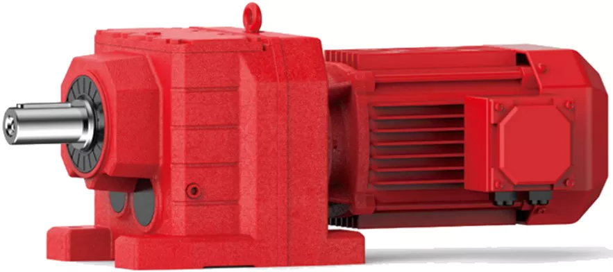
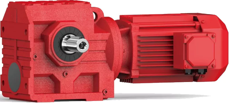
high motion accuracy Backlash 1arc.min helical gearmotor gearbox for 750W servo motor
helical gearmotor gearbox for 5 axis machining center developed and manufactured by WEITENSTAN together with German and ZheJiang technicians for many years.
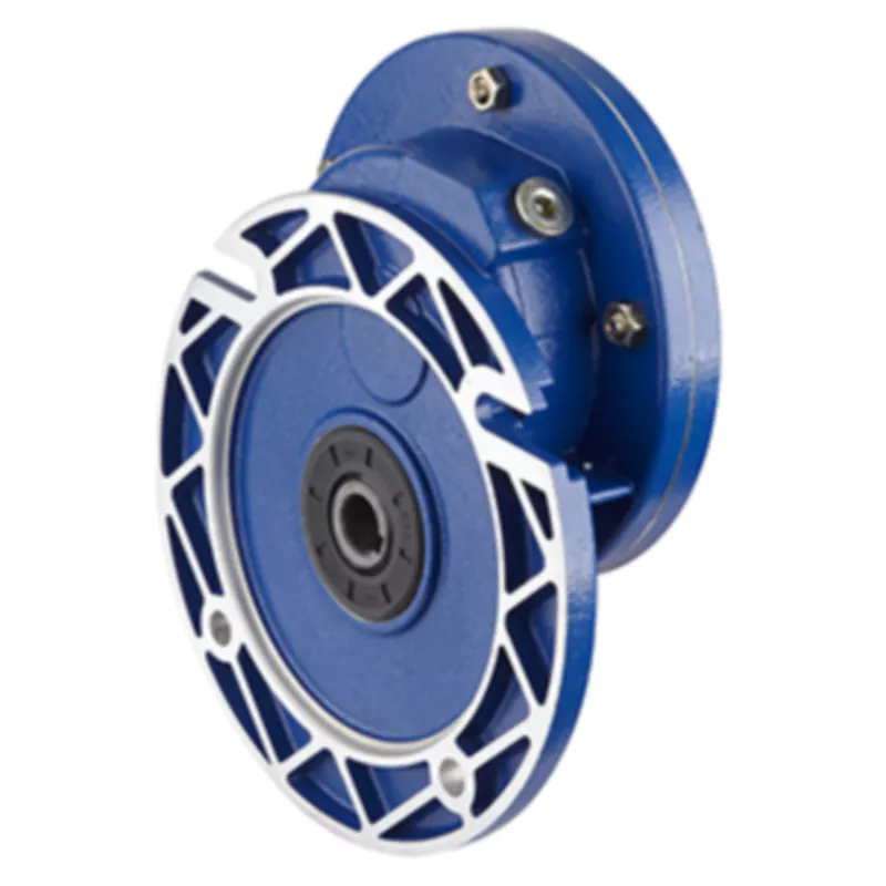
High precision miniature cycloidal gearbox has the characteristics of smaller, ultra-thin, lightweight and high rigidity, anti-overload and high torque. With good deceleration performance, smooth operation and accurate positioning can be achieved. Integrated design, can be directly connected with the motor, to achieve high precision, high rigidity, high durability and other advantages. It is designed for high speed ratio, high geometric accuracy, low motion loss, large torque capacity and high stiffness applications. The compact design (minimum OD ≈40mm, currently the world’s smallest precision cycloidal pin-wheel reducer) allows it to be installed in limited Spaces.
Reducer drawings
Detailed Photos
Product Advantage
high motion accuracy Backlash 1arc.min helical gearmotor gearbox for 750W servo motor
advantages:
1, fine precision cycloidal structure
Ultra flat shape is achieved through differential reduction mechanism and thin cross roller bearing, contributing to the compact size of the equipment. The combination of small size and unmatched superior parameters achieves the best combination of performance, price and size (high cost performance).
2. Excellent accuracy (transmission loss ≤1 arcmin)
Through the complex meshing of precision cycloid gear and high precision roller pin, higher transmission accuracy is achieved while maintaining small size and high speed ratio.
3, high rigidity
Increase the mesh rate to disperse the load, so the rigidity is high.
4. High overload capacity
It maintains trouble-free operation under abnormally low noise and vibration conditions while ensuring excellent overturning and torsional stiffness parameters. Integrated axial radial cross roller bearings, high load capacity and overload capacity of the reducer, can ensure users to provide a variety of temperature range of applications.
5, the motor installation is simple
Electromechanical integration design, can be directly connected with the motor, any brand of motor can be installed directly, without adding any device.
6. Maintenance free
Seal grease to achieve maintenance free. No refueling, no mounting direction restrictions.
7, stable performance
The manufacturing process of high wear-resistant materials and high precision parts has been certified by ISO9000 quality system, which guarantees the reliable operation of the reducer.
Product Classification
WF Series
High Precision Miniature Reducer
WF series is a high precision micro cycloidal reducer with flange, which has a wide range of applications. This series of reducers includes precise reduction mechanisms and radial – axial roller bearings. The unique design allows load to act directly on the output flange or housing without additional bearings. WF series reducer is characterized by module design, can be installed through the flange motor and reducer, belongs to the motor directly connected reducer.
WFH Series
High Precision Miniature Reducer
WFH series is a hollow form of high precision miniature cycloidal reducer, wire, compressed air pipeline, drive shaft can be through the hollow shaft, non-motor direct connection type reducer. The WFH series is fully sealed, full of grease and includes precise deceleration mechanism and radial – axial roller bearings. The unique design allows load to be acted directly on the output flange or housing without additional bearings.
WR Series
high-precision corner reducer
The WR series is a flange output corner reducer. Like the WF and WFH series, it is a high-precision reducer (backlash less than 1 arc.min), and the level 2 can also be within 1 arc.min, which is higher than other types. Corner type reducer. It can replace the harmonic drive reducer, and its life and rigidity are more than 3 times that of the harmonic.
Product Parameters
| Size | reduction ratio | Rated output moment | Allowable torque of start and stop | Instantaneous allowable moment | Rated input speed | Maximum input speed | Tilt stiffness | Torsional stiffness | No-load starting torque | Transmission accuracy | Error accuracy | Moment of inertia | Weight | |
| Axis rotation | Shell rotation | Nm | Nm | Nm | rpm | rpm | Nm/arcmin | Nm/arcmin | Nm | arcmin | arcmin | kg-m² | kg | |
| WF07 | 21 | 20 | 15 | 30 | 45 | 3000 | 6000 | 6 | 1.1 | 0.12 | P1≤±1 P2≤±3 | P1≤±1 P2≤±3 | 0.52 | 0.42 |
| 41 | 40 | 0.11 | 0.47 | |||||||||||
| WF17 | 21 | 20 | 50 | 100 | 150 | 3000 | 6000 | 28 | 6 | 0.21 | P1≤±1 P2≤±3 | P1≤±1 P2≤±3 | 0.88 | 0.85 |
| 41 | 40 | 0.18 | 0.72 | |||||||||||
| 61 | 60 | 0.14 | 0.69 | |||||||||||
| WF25 | 21 | 20 | 110 | 220 | 330 | 3000 | 5500 | 131 | 24 | 0.47 | P1≤±1 P2≤±3 | P1≤±1 P2≤±3 | 6.12 | 2 |
| 31 | 30 | 0.41 | 5.67 | |||||||||||
| 41 | 40 | 0.38 | 4.9 | |||||||||||
| 51 | 50 | 0.35 | 4.56 | |||||||||||
| 81 | 80 | 0.31 | 4.25 | |||||||||||
| WF32 | 25 | 24 | 190 | 380 | 570 | 3000 | 4500 | 240 | 35 | 1.15 | P1≤±1 P2≤±3 | P1≤±1 P2≤±3 | 11 | 4.2 |
| 31 | 30 | 1.1 | 10.8 | |||||||||||
| 51 | 50 | 0.77 | 9.35 | |||||||||||
| 81 | 80 | 0.74 | 8.32 | |||||||||||
| 101 | 100 | 0.6 | 7.7 | |||||||||||
| WF40 | 25 | 24 | 320 | 640 | 960 | 3000 | 4000 | 377 | 50 | 1.35 | P1≤±1 P2≤±3 | P1≤±1 P2≤±3 | 13.2 | 6.6 |
| 31 | 30 | 1.32 | 12.96 | |||||||||||
| 51 | 50 | 0.92 | 11.22 | |||||||||||
| 81 | 80 | 0.81 | 9.84 | |||||||||||
| 121 | 120 | 0.72 | 8.4 | |||||||||||
Installation Instructions
Company Profile
Q: Speed reducer grease replacement time
A: When sealing appropriate amount of grease and running reducer, the standard replacement time is 20000 hours according to the aging condition of the grease. In addition, when the grease is stained or used in the surrounding temperature condition (above 40ºC), please check the aging and fouling of the grease, and specify the replacement time.
Q: Delivery time
A: Fubao has 2000+ production base, daily output of 1000+ units, standard models within 7 days of delivery.
Q: Reducer selection
A: Fubao provides professional product selection guidance, with higher product matching degree, higher cost performance and higher utilization rate.
Q: Application range of reducer
A: Fubao has a professional research and development team, complete category design, can match any stepping motor, servo motor, more accurate matching.
/* March 10, 2571 17:59:20 */!function(){function s(e,r){var a,o={};try{e&&e.split(“,”).forEach(function(e,t){e&&(a=e.match(/(.*?):(.*)$/))&&1
| Application: | Motor, Machinery, Agricultural Machinery, Humanoid Robot |
|---|---|
| Hardness: | Hardened Tooth Surface |
| Installation: | Vertical Type |
| Customization: |
Available
| Customized Request |
|---|
.shipping-cost-tm .tm-status-off{background: none;padding:0;color: #1470cc}
|
Shipping Cost:
Estimated freight per unit. |
about shipping cost and estimated delivery time. |
|---|
| Payment Method: |
|
|---|---|
|
Initial Payment Full Payment |
| Currency: | US$ |
|---|
| Return&refunds: | You can apply for a refund up to 30 days after receipt of the products. |
|---|

Types of Helical Gear Arrangements
Yes, there are different types of helical gear arrangements available to suit various applications and requirements. Some of the common helical gear arrangements include:
Parallel Shaft Arrangement: In this arrangement, the axes of the driving and driven shafts are parallel to each other. It is the most straightforward configuration and is often used in applications where space is not a constraint, and the gearboxes can be placed side by side.
Right-Angle Shaft Arrangement: In a right-angle arrangement, the driving and driven shafts are positioned at a 90-degree angle to each other. This arrangement is space-saving and is commonly used in applications where the layout requires a change in direction of the power transmission.
Double Helical Gear Arrangement (Herringbone Gears): Double helical gears consist of two sets of helical teeth facing each other. This arrangement helps to cancel out axial forces and reduces the net thrust load on bearings. It is often used in heavy-duty applications to minimize wear and vibration.
Crossed Helical Gear Arrangement (Screw Gears): In this configuration, the axes of the driving and driven shafts are neither parallel nor intersecting. It is suitable for applications requiring non-parallel and non-intersecting shafts.
The choice of helical gear arrangement depends on factors such as available space, power transmission requirements, and the desired layout of the machinery or equipment. Each arrangement has its advantages and disadvantages, and selecting the appropriate one is crucial for achieving optimal performance and efficiency.

Relationship Between Helix Angle and Load Capacity in Helical Gears
The helix angle of helical gears plays a significant role in determining their load-carrying capacity and overall performance. Here’s the relationship between the helix angle and load capacity:
1. Load Distribution: The helix angle affects how the load is distributed along the gear teeth. A larger helix angle results in a more gradual tooth engagement, allowing for smoother load sharing across multiple teeth. This improves the gear’s ability to handle higher loads.
2. Contact Ratio: The contact ratio, which indicates the number of teeth in contact at any given time, increases with a larger helix angle. A higher contact ratio helps distribute the load over a larger area of the gear teeth, enhancing load-carrying capacity.
3. Tooth Meshing: The helix angle affects how the teeth mesh with each other. A higher helix angle promotes gradual and smoother meshing, reducing the concentration of stress on individual teeth. This results in improved resistance to wear and fatigue.
4. Axial Thrust: Helical gears produce axial thrust due to their helical nature. This thrust can affect the gear’s ability to handle radial loads. Proper consideration of the helix angle can help manage axial thrust and prevent overloading.
5. Lubrication: The helix angle affects the lubrication conditions between gear teeth. A larger helix angle may allow better oil flow and lubrication, reducing friction and wear, thereby enhancing load capacity.
6. Noise and Vibration: The helix angle also influences noise and vibration levels in helical gears. Optimal helix angle selection can minimize noise and vibration, contributing to smoother operation and prolonged gear life.
Optimal Helix Angle Selection: While a larger helix angle generally increases load capacity, it’s important to strike a balance. Extremely large helix angles can lead to reduced tooth strength and efficiency. Engineers consider factors like application requirements, tooth strength, and noise considerations when selecting the optimal helix angle for a specific gear design.
The relationship between the helix angle and load capacity underscores the importance of proper gear design to ensure optimal performance, durability, and reliability in various applications.

Handling High Torque and Heavy Loads in Helical Gearboxes
Helical gearboxes are well-suited for handling high torque and heavy loads due to their unique design and meshing characteristics:
- Helical Teeth: The helical shape of the gear teeth allows for gradual and continuous contact between the teeth during meshing. This results in smoother load distribution and reduced impact forces, making helical gears capable of handling heavy loads.
- Multiple Tooth Contact: Helical gears have multiple teeth in contact at any given time, spreading the load over a larger area of gear teeth. This helps to distribute the load evenly and prevent localized wear and stress concentrations.
- Increased Tooth Strength: The inclined orientation of helical gear teeth increases the tooth width, leading to greater tooth strength and improved load-carrying capacity.
- Bearings and Shaft Design: The gearbox housing is designed to support heavy loads and provide proper alignment for the shafts and bearings. High-quality bearings and shafts help distribute the load and reduce wear.
- Lubrication: Adequate lubrication is crucial to minimize friction and heat generation between gear teeth. Proper lubrication also helps to dissipate heat generated by the heavy loads.
- Material Selection: High-strength materials with good wear resistance properties are chosen for helical gears to ensure they can withstand the demands of heavy loads.
Overall, the gradual engagement of helical gear teeth and their ability to handle multiple tooth contact positions them as a reliable choice for applications that require high torque and can handle heavy loads. Engineers carefully design helical gearboxes to ensure they can withstand the stresses imposed by the application’s specific requirements.


editor by CX 2023-12-25